CHI035 power board questions

satrapus

Member
Hello ,
I have 2 questions regarding the CHI035 board...

1)
I want to power it with a 12v car battery.

The pdf document states that for a single Battery Pack 7.5-12v I must use a regulator.
My car battery is around 12.7V and when my engine is running it's around 13.5v.

Will this be a problem as it's above the specified 7.5-12v range?

2)
My project involves a slow revs 12v dc motor.
I don't need the forward/reverse functionality of the optional L293D chip that the CHI035 supports.
However there is a possibility that my motor could become overloaded or even jam during operation.
As I've never used the L293D chip before I don't know if it supports motor cutout ?
Ideally I want the motor to cut out over 1.5A.
Any suggestions for a solution for this?

Much appreciated
 

rossko57

Senior Member
The pdf document states that for a single Battery Pack 7.5-12v I must use a regulator.
My car battery is around 12.7V and when my engine is running it's around 13.5v.
Then you'll be using a regulator - the suggested type is 78L05. The question is, will the 78L05 be okay at 15V? Consult a 78L05 datasheet.
There is also the heat generated by the regulator - the higher the input voltage, the more heat. The 78L05 will protect itself from overheating, but of course the output will not be what you wanted. Just to power a picaxe, I would not expect any problems here.

You also need to consider whether the L293D (if that is what you use) will cope with car power. Again, check a datasheet.

Car power supplies are generally considered "dirty" for electronics - noisy and variable. Be sure to use good earth wiring and fit all capacitors.

However there is a possibility that my motor could become overloaded or even jam during operation.
As I've never used the L293D chip before I don't know if it supports motor cutout ?
Ideally I want the motor to cut out over 1.5A.
Depends what you mean by cutout. The L293D will limit its output to around 600mA, thats still enough to make lots of heat at both chip and motor. This is not adjustable.
The Picaxe could be made to turn it off of course, but you would need to design a means to detect the current condition.
EDIT - depending what the task is, your program could limit how long the motor is alloed to run for, to reduce cooking.

On the face of it, the L293D is not suitable for driving a 1.5A motor.

If you only need on/off, you could consider a simple relay or transistor switch, with a current-detection or limiting design.
 
Last edited:

westaust55

Moderator
The 78L05 voltage regulator can handl input currents up to 30 volts so operation from a 12 to 14 volt source is not a problem.
If there is a significant current draw relative to regulator rating a heat sink can be required.

The L293D has a max current rating of 600mA
The FET "high" power transistors are the components rated at 1.5 amps.

None of these parts (L293D or the FETs) have current limiting.
 
Last edited:

satrapus

Member
Thanks fellas
I won't use the L293D then as I just need on/off for motor.
Will try to figure out a way to cut out motor with picaxe as I'll like to avoid any pcbs other than the powerboard itself.
Motor draws way less then 600mA but I want a fail safe if something gets jammed.
 
Last edited:

Circuit

Senior Member
Hello ,
My project involves a slow revs 12v dc motor.

Ideally I want the motor to cut out over 1.5A.
Any suggestions for a solution for this?

Much appreciated
As Rossko57 said, it depends upon what you mean by "cut out". One device that is specified to cut out when a current limit is reached but to automatically reset after 20 seconds or so is the polyfuse - and this is very low cost. This datasheet http://www.rapidonline.com/pdf/26-4600e.pdf gives you details of the holding current and the "always trip" value. Cut-outs can be either latching; requiring a physical reset switch of some sort or a power-down cycle to reset or they can "hiccough". The polyfuse is of the latter type; it will repeatedly cycle until the overload is removed. You will note that the datasheet specifies them for automotive operation.

You may obtain further help from this website by being a little more specific about your application; what is the motor moving? What is needed to turn it on? etc.
 

westaust55

Moderator
An option that I have used for simple motor current limiting (in an analogue circuit using BJT transistors) that could also be used as a simple shutdown mechanism would be to include a resistor metween the motor and ground (0 volts).
If for example you use a 1 Ohm resistor then at 1.5 Amps there will be 1.5 Volts (V = I * R ) across the resistor. The PICAXE can monitor the voltage with an ADC input (remove any pull-up or pull-down resistors first) and using the READADC command you can shut down until a reset is performed.

I am guessing that the motor is the drive for your "Chum"/Burley dispenser:
http://www.picaxeforum.co.uk/showthread.php?27022-quot-Chum-Dispenser-quot-solution-with-picaxe-advice-needed-by-noob
 

satrapus

Member
As Rossko57 said, it depends upon what you mean by "cut out". One device that is specified to cut out when a current limit is reached but to automatically reset after 20 seconds or so is the polyfuse - and this is very low cost. This datasheet http://www.rapidonline.com/pdf/26-4600e.pdf gives you details of the holding current and the "always trip" value. Cut-outs can be either latching; requiring a physical reset switch of some sort or a power-down cycle to reset or they can "hiccough". The polyfuse is of the latter type; it will repeatedly cycle until the overload is removed. You will note that the datasheet specifies them for automotive operation.

You may obtain further help from this website by being a little more specific about your application; what is the motor moving? What is needed to turn it on? etc.
The motor will be driving a small sort of conveyor belt on a boat. Hooks on the belt will grab hold of bait pieces and throw them into the sea.
Should something jam or someones hand accidentally get caught on a hook I just require the whole system to stop. A hard reset by means
of flicking main switch off/on will restart everything.
Please forgive the nature of my questions. As you can probably tell electronics is very new to me.
This is a reason why I chose the power board as it simplifies a lot of issues, well at least I hope it will.
 

premelec

Senior Member
Polyfuses work ok with some time delay - you can cheaply make a current regulator with a single LM317T and resistor [see it's data sheet] - it will have some voltage drop but current limits immediately.
 

goom

Senior Member
As I understand it, satrapus wishes to completely cut the motor drive on detecting an overload, and keep it off until a manual reset is initiated. Neither a Polyfuse or current limiter would achieve this.
Motor current could be measured by inserting a low value resistor between the motor and ground as suggested by westaus55, and measuring the voltage at the motor/resistor junction via READADC. Clearly the program would need to poll the ADC in a loop, and stop the motor and await operator input if the voltage exceeds the threshold of 0.5V (for 0.5 Ohms and 1.0A). It may be necessary to delay the polling on motor start-up due to the initial high inrush current.

I believe that you can run the two drivers in the L293D in parallel to get a 1.2A capability, so this may eliminate the chance of releasing the "magic smoke" when combined with a 1.0A trip limit.
 

rossko57

Senior Member
With 'hooky' parts and squishy cargo on the conveyor, is there any requirement for a reverse action in case of jam? I would think the belt might be pulled backwards easily by hand, but now's the time to decide.

You might get away with a degree of smarts in your programming here. You have a "bait-passing" detector. If the motor is running but you don't detect changing presence/absence in the way you expect within certain time windows, there is a jam. If the driver circuit can tolerate a few seconds stalled overload (which would be good design anyway), will that do?
 

hippy

Technical Support
Staff member
It is a better option to prevent injury than detect when injury may be in progress. While stopping the motor when it stalls may be something to strive for, the better option is to not allow people to get caught up in the machine in the first place.

That could perhaps be easily achieved by enclosing the conveyor belt, in perspex if one needs to see the belt, and having a mechanism which shuts the motor off if that cover is opened, only allows the motor to run when the enclosure is closed.

That safety cut-out should be entirely hardware based, a simple switch or two may be enough, so even if the stall detection or software handler fails then it is still a safe system to use.

Safety is an important issue, and is particularly onerous when being the one responsible for it, the one who gets blamed, sued, even imprisoned, when things go badly wrong.
 

satrapus

Member
Sorry for delay in replying, all your comments are very much appreciated.
My chi035 board and 18m2 have arrived so I'm getting to grips with it.
The motor emergency cut out is put on hold for now.
I have some mechanical problems in the design that are a higher priority.
 

satrapus

Member
Here's my third chi035 question :D

I want to minimise components off the power board as much as possible.

006.JPG
I'm using a 3 way switch to set system mode.
As I have lots of input pins to spare, would the above setup be ok paired with code along the lines of:

; INPUTS
symbol swchPosTimed = c.6
symbol swchPinTimed = pinc.6
symbol swchPosCont = c.7
symbol swchPinCont = pinc.7

MainLoop:
do
if swchPinTimed = 1 then
; Timed mode
else if swchPinCont = 1 then
; Continuous mode
else
; OFF
endif
loop
 

westaust55

Moderator
I believe what you propose will work.
Another option could be to use pins C.0 and C.1 for simplicity and then the SELECT CASE program structure:
Code:
SYMBOL mode = b0

Mode = PINSC AND %00000011 ; check pins C.0 and C.1 and mask off higher pins
SELECT CASE Mode
  CASE 1 
        ; do timed mode stuff
  CASE 2: 
        ; do continuous stuff
  ELSE
        ; shutdown/stop/off – here if neither pin high  or heaven forbid,  both pins are high
  ENDESELECT
If there is going to be a lot of code under each mode routine and you require rapid mode change then consider also using the interrupt (SETINT) mechanism.
 

satrapus

Member
Great, thanks for you reply on both threads. Your help is very much appreciated!

I can't use C.0 anc C.1 as I need to have a pot connected on one of them.

I will test the system as is, with the big old loop, and see how it performs.
Will probably need interrupt as you suggested as there's a whole lotta things going on.

I am almost ready to hook everything up to my chi035 and start testing the system as a whole. Very excited :eek:


I just have the following issues to resolve:

1) is my ir Led on/off code working:
irLedOn:
if irLedPin = 0 then
pwmout irLed, 25, 51 ; 38000Hz at 50% @ 4MHz
endif
return

irLedOff:
if irLedPin = 1 then
low irLed
pwmout irLed, off
endif


2) which input pin to choose for my photo modulator
I think c2 is best out of c2,c3 and c4 that remain free


3) ideally I'd like to have all the wires coming into the board screwed in, not soldered
The pot connection is a bit tricky.
I don't know if the solution on the right is acceptable, never done this before but at least my soldering is now improving.

003 copy.jpg
 
Last edited:

JimPerry

Senior Member
Should be Ok - two gotchas though. Make certain that the terminal block wire IN is the correct way around (I've received stuff from E***y where it was impossible to put a wire in) and you can "snip" a surplus connector off (before soldering). :cool:
 

satrapus

Member
I will give that a go as the connector that sticks out sure is a bit of an eye sore.
Not sure how cleanly it will snip off though...

Here's a monumentally stupid question related to my 3 way switch being wired to c6 and c7 pins.
The code works as it should but when I used the multimeter it seems that all input pins are at 5V and activating the switch drops voltage to 0 on that pin.
In other words
if swchPinTimed = 1 then ; 1 is 0V and 0 is 5V - should it not be the other way around?
 
Last edited:

hippy

Technical Support
Staff member
The code works as it should but when I used the multimeter it seems that all input pins are at 5V and activating the switch drops voltage to 0 on that pin.
In other words
if swchPinTimed = 1 then ; 1 is 0V and 0 is 5V - should it not be the other way around?
C.6 and C.7 have pull-downs and you are switching the +V into those, so it should be that C.6 and C.7 are by default low, a switch activation would be expected to take the pin high.

It could be the switch is rather unusually wired internally, but perhaps you simply have it upside down ?

Taking the switch out of circuit and doing a resistance / continuity check will determine its internal wiring.
 

satrapus

Member
Hi Hippy!

It's a standard switch alright.
Something weird is going on here and I suspect it's me being stupid.

I am using the chi035 with a 12v supply.
I installed a 78L05 on the board, removed the wire link below it.
I also removed 10k resistors R7 and R8 so that I can use a pot on C0.
When I power up the board inputs pins c0 and c1 show 0v and all the others are showing 5v.

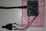
Here's a pic. Those are not my hands btw. My 5 year old was helping out so that I could take a snap :)
001.JPG

Is this as it should be or is everything reversed?

The oddest thing is that
if pinc.6 = 1
is true when voltage is 0 on the pin due to 3 way switch being on on that pin ????

Thanks
 
Last edited:

hippy

Technical Support
Staff member
It seems to be a matter of how you are measuring things.

Your reading looks correct. Between the input pin and +V there is nearly 5V, which indicates the pin is virtually at 0V.

Connect the black lead to a 0V point and then measure C.6 and C.7 with the red lead. That will give a genuine reference from 0V and should show approximately 0V to C.6 and C.7.
 

satrapus

Member
That's a relief. At least everything is as it should be and working correctly.

Where is the 0V point on the chi035? (embarrassed)
I only see 2 v's in the corner next to c.0 on the input side of the board.

I was measuring the output pins the same way and was getting readings that I expected (0v when low and 12v when high)
That's what's confusing me.
 

hippy

Technical Support
Staff member
The 0V point one can always rely on is where 0V comes in from the power supply but the datasheet also shows where other 0V points are ( marked "G" ). In your photo, the screw terminal to the right of C.7 should be a 0V.
 
Top