Gradiometer

MACKE

New Member
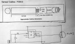
Hi I am thinking of building a gradiometer for archeology. I will be using 2 FGM3 sensors and an SCL007 ASIC from Speake & Co. in the UK.The SCL007 is a PIC 16C54A – 20/P programmed by Speake & Co. for use with the FGM3 sensors and provides a digital output for data logging. I am told the output is an 8 bit parallel word plus a sign bit to show which sensor is sensing.
My problem is that I can build the analog part without any problems, but i haven't had any experience of digital electronics.
Can anybody help with the digital interface to the SCL007 chip. It needs to have an LED display. The programme would need to allow date input ,log file naming and grid size selection on startup. Typically the grid size would be 20 x 20, or 40 x 40 meters with a reading being taken every meter. It would then need to allow for calibration. You could either take manual readings every meter or allow for automatic logging every meter. This would need calibrated to your walking pace.

Below is a link to an article describing the analog build. Also attached is the spec sheet for the FGM3 sensors.


http://www.geotech1.com/pages/mag/projects/fmx1/fmx1.pdf

Thank you

Ken
 

Attachments

Buzby

Senior Member
Hi Macke,

Welcome to the forum !.

That SCL007 looks easy to interface to, it would be no problem for a PICAXE.

An 'off the shelf' PICAXE board ( maybe AXE401 ) can provide all of the digital components ready mounted, including a EEPROM to store thousands of results.

It looks like a cool project.

Good luck,

Buzby
 

julianE

Senior Member
Hello Macke,

I used the FGM-3 about a year ago, very good sensor. Very easy to interface to the Picaxe. I will need to dig up my notes but i found a quick test program I used to test the sensor.


'Picaxe 08M2

setfreq m16
main:
count c.1, 750,W1
pause 50

sertxd (#W1, " ", CR,LF)
goto main

I have not run it in a while but i can dig up the part and breadboard it.

Of course, for your purposes you will need a bigger chip then the 08M2 tho you could probably make it work if you used a serial OLED display from
RevEd, would make for a very compact device.

The folks on this forum are exceptionally helpful, good luck with your project.
 

MACKE

New Member
Hi that would be brilliant. I need all the help I can get. I do have a breadboard and a 20M2.

Ken
 

eggdweather

Senior Member
He's given you what you need, the FGM03 has typically 3-pins +5v, Gnd and pulse out, so use a PICAXE to measure pulse width from the centre pin and you have a gradiometer.
 

julianE

Senior Member
Sorry for the long delay. I breadboarded the circuit, using the program i posted earlier, the values i'm receiving with the FGM3 sensor vertical is about 11000, if i place a piece of metal near the sensor the value will vary by about 2000 and as high as 3000 depending on the distance, so values in 8000-9000 range. 08M2 FGM3.jpg

on the circuit i forgot to draw in a .1 microfarad capacitor across the power leads of the sensor.
the sensor does need a well regulated power supply.

I only have one of the FGM 3 sensors so i can't replicate the circuit you attached. the circuit you sent relies on the two sensors nulling each other out. it relies on the difference between the readings of the sensors to tell if there is a magnetic abnormality. you can probably use the picaxe to read each sensor, store the values in two variables and then do a comparison between the sensors and display the value or activate a buzzer if threshold is reached. lot of experimenting or you can just build it as described in your attachments and use the picaxe to interpret the data coming out.
 

julianE

Senior Member
I have been working with the FGM 3 sensor hoping to be able to detect solar storms. the sensor is very impressive but I'm having a difficult time translating it's output to units like nanoTesla. The output from the sensor is supposed to be ~120 KHz to ~50KHz although there are other places in the datasheet stating 0 to 20 Khz.

The average reading i'm getting from the sensor is 10200, I'm interpreting that to mean 10200 Hertz. I'm running this on an 08M2,

setfreq M32
count c.1, 8000,W1

My thinking, count command is counting for 1 second when 08M2 is running 32 Mhz hence the 8000 in the command.

Am I thinking this out correctly?
 

AllyCat

Senior Member
Hi,

The output from the sensor is supposed to be ~120 KHz to ~50KHz although there are other places in the datasheet stating 0 to 20 Khz.

The average reading i'm getting from the sensor is 10200, I'm interpreting that to mean 10200 Hertz.
No. The 20 kHz refers to the highest possible detectable "modulation" (rate of change) of the field strength. With a 1 second "count" period, yours will/must be less than 0.5 Hz.

The data sheet seems quite specific that the output is between 50k and 120k Hz, so your counter is probably overflowing (at 65536 Hz). Therefore the output is probably around 75.7 kHz. It would be better to measure for a shorter period and then calculate the frequency accordingly. Note that you must use a 32 kHz clock for the PICaxe COUNT command to give the required > 100 kHz bandwidth.

Cheers, Alan.
 

julianE

Senior Member
Thanks Alan for clearing up my confusion. I first assumed that 50Khz to 120Khz was the output from the sensor that's why i used, setfreq M32, thanks for clearing up the 20 Khz number for me.

Note that you must use a 32 kHz clock for the PICaxe COUNT command to give the required > 100 kHz bandwidth.
I'm fairly sure you mean 32 Mhz clock.

I'm only checking the sensor every minute so I would think a 1/2 second count should be ample or would I get a better resolution leaving it as is and just adding
65536 to the value coming from the picaxe. The data is being sent to a PC so I can do the math there, from the PC I send it to thingspeak.com for graphing.

to sum it up,

let it overflow and deal with calculating correct frequency in the PC

setfreq M32
count c.1, 8000,W1


or
get the full number from the sensor and multiply by 2 in the PC to figure out the frequency.

setfreq M32
count c.1, 4000,W1


I will reduce the count to 1/4 of a second period just to check what the correct values are before I rely on using the overflowed numbers. The sensor will be oriented in one direction so the numbers will stay in a relatively small range.
 

hippy

Technical Support
Staff member
Note that you must use a 32 kHz clock for the PICaxe COUNT command to give the required > 100 kHz bandwidth.
I think you may have meant MHz ?

With a COUNT for a 1ms period it should count 75 for 75kHz, 100 for 100kHz etc. Untested ...

Code:
#Picaxe 08M2
#Terminal 38400
SetFreq M32
Do
  Count C.1, 8, w1
  SerTxd( "Freq=", w1, "kHz", CR, LF )
  Pause 8000
Loop
 

AllyCat

Senior Member
Hi,

Yes, my kHz for the clock frequency was a slip of the finger (or brain).

Strictly, with a range of 50 - 120 kHz, you can't differentiate, say, 51 kHz (without overflow) from 116.536 kHz. But if the field is reasonably constant then it may not matter.

The overflow theoretically permits a higher resolution measurement. But the timing "window" set by the PICasxe clock is unlikely to be any better than +/- 0.1%, so 100ms should be more than enough in practice. Do you have any idea what level of accuracy (stability) you need to achieve ?

Multiplying by 2 or 10 in PICaxe Basic is not exactly difficult, so I'd rather do it there than in a "bodge" in the PC program.

Cheers, Alan.
 

julianE

Senior Member
Thanks for all the replies.
Alan, I'm at the very beginning with this project, not sure about accuracies at all, I sort of wanted to put some units on the measurements to have some correlation with real world.
I ran the numbers against the datasheet and i'm certainly in the ballpark with the 75.7 Khz I'm measuring from the picaxe. According to the datasheet the 0 value is at 71.428 Khz, I have the sensor in an approximate east to west orientation, I have it all fastened down and plan on tuning it in better in near future. You are right that the tiny difference introduced by scaling my count to 1/2 second would not matter much compared to all the other tolerances with the sensor/picaxe. The sensor is so sensitive it will sense a large vehicle passing 10 meters away. The sensor is also affected by temperature, another variable. I am sending the data from the sensor to thingspeak, https://thingspeak.com/channels/43904.

There are a few sites on the web that publish Magnetometer readings, I'll see if my numbers are close, looking for delta, not so much exact numbers.
 
Top