A theoretical idea
- Thread starter oracacle
- Start date
My thoughts and my thoughts only. You can build a chronograph as in the original post, a chronograph will give you projectile velocity which is what it is designed to do. A chronograph will consist of two sensors also known as screens or sky screens in ballistic chronographs. The chronograph will measure the elapsed time between a start and stop pulse, the Velocity is then calculated based on the time it takes the projectile to travel a known distance. Velocity = Distance / Time and that is that. A good chronograph will measure using a minimum of two screens.
If you just want to fire a camera flash when a projectile passes a given point you really only need a single sensor placed a short distance in front of the object to be photographed. Projectile passes sensor and flash fires or projectile passes sensor, a short delay and flash fires.
Be it a chronograph or a or a circuit to fire a flash it starts with a sensor, be it a single sensor or two sensors it starts with a sensor. So the sensor is likely a good place to start. Today's ballistic chronographs use pretty sharp optical sensors to detect a bullet moving along at 4,000 FPS (Feet Per Second) to a much slower pellet or BB traveling along at 350 FPS. The sensor is in my opinion the most difficult part to get this right. Let's take a look at a pellet for example fired from a pellet gun. Typical pellets come in a few sizes with .177 caliber (4.5mm) and .22 caliber (5.5mm) being among the popular sizes. Not a heck of a lot there to detect, especially considering the working area of sky screens.
The earliest sky screens long before optical transistors and photo diodes consisted of a piece of paper with a grid of generally #30 AWG fine wire spaced according to bullet diameter. The wire was laid out on a single piece of paper with .1" spacing for example for small diameter bullets like .177 or .22. The end result looked like this image:

Obviously these screens were a one time good deal. The screen had a resistor in series with it and one end went to ground and the other connection to a maybe 10K resistor to Vcc or power +. Once a screen was shot it was replaced and the shot screens were actually repaired several times before being discarded. They were simple, they were crude and they worked just fine. There was no problem with light or dark or ambient light. When the projectile cut the wire the junction of the sensor screen (which closely resembled a screen) and the series resistor was going high and that was a given.
Things evolved to electronic optical sensors and keep in mind that little tiny projectile passing over an optical sensor isn't easy to catch or detect. Optical sensors basically come in a few flavors, each having their good and bad points. Most sensors rely on daylight and catch the glint of the projectile as it passes over the sensor. Below is an example of some sky screens that rely on daylight:
Obviously this sort of configuration won't work for you since you want to trigger a flash in darkness with an open shutter. The best sensor detector in my opinion for your application is an IR emitter detector combination which will likely work quite well in darkness. The problem still remains detecting the tiny projectile. Generally this is done using several IR emitters like around 4 or 5 and several IR detectors like around 4 or 5 carefully configured in a square with emitters on top and detectors on the bottom. This is also not an On / Off affair. The emitters are wired in a series configuration and the detectors are paralleled. The projectile causes a slight voltage change which is then amplified and conditioned to get a well defined pulse. Each projectile crossing the sensors causes a small voltage change, that change is then amplified and passed on to a level detector and eventually we get a good clean usable pulse. The beauty of IR is when working in darkness it's great!
Once you have a sensor pulse the rest is easy. Driving a circuit like a D Flip Flop is no problem and further signal conditioning is no problem. The sensors, in my opinion, are the difficult part. What I would do if I were doing this project is start with a wired board as I originally mentioned.
Just My Take....
Ron
If you just want to fire a camera flash when a projectile passes a given point you really only need a single sensor placed a short distance in front of the object to be photographed. Projectile passes sensor and flash fires or projectile passes sensor, a short delay and flash fires.
Be it a chronograph or a or a circuit to fire a flash it starts with a sensor, be it a single sensor or two sensors it starts with a sensor. So the sensor is likely a good place to start. Today's ballistic chronographs use pretty sharp optical sensors to detect a bullet moving along at 4,000 FPS (Feet Per Second) to a much slower pellet or BB traveling along at 350 FPS. The sensor is in my opinion the most difficult part to get this right. Let's take a look at a pellet for example fired from a pellet gun. Typical pellets come in a few sizes with .177 caliber (4.5mm) and .22 caliber (5.5mm) being among the popular sizes. Not a heck of a lot there to detect, especially considering the working area of sky screens.
The earliest sky screens long before optical transistors and photo diodes consisted of a piece of paper with a grid of generally #30 AWG fine wire spaced according to bullet diameter. The wire was laid out on a single piece of paper with .1" spacing for example for small diameter bullets like .177 or .22. The end result looked like this image:
Obviously these screens were a one time good deal. The screen had a resistor in series with it and one end went to ground and the other connection to a maybe 10K resistor to Vcc or power +. Once a screen was shot it was replaced and the shot screens were actually repaired several times before being discarded. They were simple, they were crude and they worked just fine. There was no problem with light or dark or ambient light. When the projectile cut the wire the junction of the sensor screen (which closely resembled a screen) and the series resistor was going high and that was a given.
Things evolved to electronic optical sensors and keep in mind that little tiny projectile passing over an optical sensor isn't easy to catch or detect. Optical sensors basically come in a few flavors, each having their good and bad points. Most sensors rely on daylight and catch the glint of the projectile as it passes over the sensor. Below is an example of some sky screens that rely on daylight:
Obviously this sort of configuration won't work for you since you want to trigger a flash in darkness with an open shutter. The best sensor detector in my opinion for your application is an IR emitter detector combination which will likely work quite well in darkness. The problem still remains detecting the tiny projectile. Generally this is done using several IR emitters like around 4 or 5 and several IR detectors like around 4 or 5 carefully configured in a square with emitters on top and detectors on the bottom. This is also not an On / Off affair. The emitters are wired in a series configuration and the detectors are paralleled. The projectile causes a slight voltage change which is then amplified and conditioned to get a well defined pulse. Each projectile crossing the sensors causes a small voltage change, that change is then amplified and passed on to a level detector and eventually we get a good clean usable pulse. The beauty of IR is when working in darkness it's great!
Once you have a sensor pulse the rest is easy. Driving a circuit like a D Flip Flop is no problem and further signal conditioning is no problem. The sensors, in my opinion, are the difficult part. What I would do if I were doing this project is start with a wired board as I originally mentioned.
Just My Take....
Ron
What about turning the concept around.
Have the PICAXE read an input signal from, say, a simple manual push button. Use this to trigger an interrupt (or just wait for the input pin to go high/low in a loop). Within the interrupt routine, turn on an output to some sort of actuator which will fire the air rifle.
As has been previously suggested, the time of flight of the pellet is probably quite consistent, as would be the time between the output signal and the firing of the rifle. By trial and error, build in a suitable delay between sending the fire signal and triggering the flash. A potentiometer feeding an ADC input could be used to manually adjust the delay.
No sensor required.
The mechanism to pull the rifle trigger would need some thought. Some sort of linear actuator or servo comes to mind.
Alternatively, what about an acoustic sensor to detect the firing. Air rifles do make a distinctive and reasonably load sound when discharged, so it should not be too difficult to convert a microphone output into a pulse which can be detected by the PICAXE. Fine tuning of the delay could be accomplished by the distance of the rifle from the microphone and/or through a potentiometer as mentioned above.
reloadron I am have ordered the part to try and replicate the IR screens in the nut and volts article, hopefully should be with me soon.
goom the idea is to try and take some of the guess work out of the system. the current flash controller can add pretty much any delay I like which is part of the reason I am using the pulsing (sensor input on a.0 and a.1) - so this become another plug in sensor for the system. I already have an acoustic sensor (ie sound detector) that can detect just about anything I want it too, even filter out background noise and only listen for load sounds (like a balloon popping) this was stated in the op.
we just seem to be cycling through the same suggestions to simplify the project - where the fun in simple, make it complex force yourself to learn things, and progress into the future. image if we the human race has stuck with keeping it simple all the time, we would still be using stone axes and would only have primitive clotting, no computers no machines no progress would ever get made if we always kept it simple. granted often simple is good but little progress is made when doing it that way - the easy way.
"We choose to go to the moon. We choose to go to the moon in this decade and do the other things, not because they are easy, but because they are hard, because that goal will serve to organize and measure the best of our energies and skills, because that challenge is one that we are willing to accept, one we are unwilling to postpone, and one which we intend to win, and the others, too." - JFK
That N&V article is really a very good write up on the subject and how these sensors actually work. The circuit itself is one I really like and should work out real well. I like being able to use IR verse daylight. The chronograph I pictured is about 20 years old now and still works real well. Today's systems are cool because many offer the ability to change the sensors for IR or daylight and IR is useful indoors. Today's units also allow in the better ones the ability to interface with a laptop.reloadron I am have ordered the part to try and replicate the IR screens in the nut and volts article, hopefully should be with me soon.
Anyway, I am really enjoying this thread and look forward to more pictures.
Ron
techElder
Well-known member
"We choose to go to the moon. We choose to go to the moon in this decade and do the other things, not because they are easy, but because they are hard, because that goal will serve to organize and measure the best of our energies and skills, because that challenge is one that we are willing to accept, one we are unwilling to postpone, and one which we intend to win, and the others, too." - JFK
Unfortunately for us poor bastards that have been left to pay for it all while they find more ways to dump our family's unearned income into space and beyond.
Simple is better if it comes from working out the problem in your mind's design process. No need to keep reinventing the wheel to make something that has never been made before. Does that make sense?
EDIT: Sorry for going so far off topic, but JFK quotes tend to boil my innards.
Last edited:
JimPerry
Senior Member
Banks and G**gle don't pay squit - etc etc OT really
Unfortunately for us poor bastards that have been left to pay for it all while they find more ways to dump our family's unearned income into space and beyond.
@Oracle
Just some rambling thoughts at the moment.
1. Ask the Dealer to measure the velocity of the pistol.
(I'll guess between 300 - 400 f.p.s. with a 7gr pellet)
2. Add a photodetector to the end of the pistol barrel,
directly across the exit hole.
Use say a BPW34 and a cheap Laser.
Base your empirical measurements on the "exit" signal.
And unless you pay serious money, do not expect a
highly consistent pattern from a basic CO2 cylinder pistol.
My sub £90 pistol shows a 20 - 30 fps spread.
My Weihrauch 100 rifle shows <1 fps spread,
but cost considerably more.
e
Last edited:
eclectic I am currently thinking about a cheapo pistol for sub 90 quid, part of the reason for leaning towards the chronograph. providing I leave enough distance between the pistol and the item I should be able to calculate the travel time on the fly meaning that each shot should be a money shot.
on a side note, most of the parts for the screens have arrived, however I would some feed back on the IR transmitter side of things. the N 'n' V article shows them being fed from 9.6v (I am using 5v) through a constant current source (LM317), however did not order any LM317s, the data sheet indicates the have Fv of 1.7v, and max Fi is 100mA - I was thinking about running them at more like 50mA which is from what I understand is the same as the in the article. any advances on this - I will have to order some ~66ohm resistors for this as it not a size I normally keep.
ir diode data sheet
http://www.mouser.com/ds/2/149/QEE123-191597.pdf
also some estimations on the size of the screens would be helpful too.
Reading the article he does mention he used a forward current for the string of 46 mA. All four IR emitters are in series. Running with 50mA I would configure the LEDs as follows:
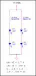
You would be running the 4 LEDs in two series pairs off 5 volts with a total current of 100 mA for all four IR emitters.
As to dimensions? I would likely go maybe 10" X 10" with the IR emitters and detectors equal distant spaced top and bottom (emitters on the top).
Ron
You would be running the 4 LEDs in two series pairs off 5 volts with a total current of 100 mA for all four IR emitters.
As to dimensions? I would likely go maybe 10" X 10" with the IR emitters and detectors equal distant spaced top and bottom (emitters on the top).
Ron
geezer88
Senior Member
Much of this thread has dealt with figuring out when to fire the flash based on the time of arrival of the bullet. I've taken a number of photographs of bullets hitting various objects, and eggs splatting on concrete, and other interesting destructive things. In my experience, finding the instant of impact is only part of the photographic challenge. The few milliseconds after impact is more interesting, and depending on what effect you want to capture, it will be a matter of finding the right delay. The object in question undergoes a huge transformation from a solid object to mush or mist or whatever, and the degree of destruction can't be calculated but needs to be found with multiple experimental shots. (Unless you are lucky enough to afford a high speed movie camera, then simply pick your favorite frame.)
Anyway many on this thread have suggested the audio trigger. It works great. Then, to adjust for the best picture, simply move the microphone for a 1msec delay per foot of distance.
Above all, have fun with it. The chronographs are neat in their own right, but certainly not necessary for this project.
tom
reloadron, I thought about that while I was at work last night. still don't have the correct size resistors but I am leaning towards doing it that way.
geezer88, I know that some test shots will be needed, the balloon shot in the op needed about three shot prior, I am still cleaning up the talc now. the idea is to remove some of the guess work so instead of - sound detected>guess time to item>guess delay after arrival>fire flash I will be able to - detect projectile>calculate speed and time to arrive at item>guess delay arrival>fire flash. I can alter the delay not matter what happens without moving the mic by simply altering the pause duration which is already possible with the controller as it stands.
no matter what happens I need to know how long it takes for the projectile to get from the weapon to the item, and the best way it seem is with at least one screen. and with the information that eclectic provided about variation of speed in a cheap gas canister power air piston, calculating time of flight on the fly should, in theory at least, be the most reliable. do it this way would mean that if the object is 2.5m away and can simply add the time instead hoping that its going to fire the same as it did the time before - ie if the projectile is on the go slow for what ever reason the system wont fire too soon, or too late if a fresh canister is installed.
elektriker
New Member
Hello oracacle!
Do you want to photograph those pictures?
the projectile leaves the barrel straight from an old air rifle.
Do you want to photograph those pictures?
the projectile leaves the barrel straight from an old air rifle.
Attachments
-
 171.4 KB Views: 21
 -
 166.4 KB Views: 21
bfgstew
Senior Member
I can see your logic Oracle and admire your tenacity in seeking the solution to this.
I would go down the simple route, a tube that fits the end of the muzzle, 2 'gates' an exact know distance apart, 1st gate starts a timer, the 2nd stops it, this gives you the muzzle velocity. The 'target' is a known distance fron the muzzle, simple math should give you the delay for the flash to fire, this is all that needs to be triggered as I am presuming the camera will have the shutter open ready to catch the action? This will allow for any variation in C02 pressure, differing pellet weights, temperature, air pressure etc etc. As long as the distance from muzzle to target is known this would work IMO.
I would go down the simple route, a tube that fits the end of the muzzle, 2 'gates' an exact know distance apart, 1st gate starts a timer, the 2nd stops it, this gives you the muzzle velocity. The 'target' is a known distance fron the muzzle, simple math should give you the delay for the flash to fire, this is all that needs to be triggered as I am presuming the camera will have the shutter open ready to catch the action? This will allow for any variation in C02 pressure, differing pellet weights, temperature, air pressure etc etc. As long as the distance from muzzle to target is known this would work IMO.
techElder
Well-known member
Well, bfgstew, that purty much restates everything in the first few posts. Good job! ")
I can see your logic Oracle and admire your tenacity in seeking the solution to this.
I would go down the simple route, a tube that fits the end of the muzzle, 2 'gates' an exact know distance apart, 1st gate starts a timer, the 2nd stops it, this gives you the muzzle velocity. The 'target' is a known distance fron the muzzle, simple math should give you the delay for the flash to fire, this is all that needs to be triggered as I am presuming the camera will have the shutter open ready to catch the action? This will allow for any variation in C02 pressure, differing pellet weights, temperature, air pressure etc etc. As long as the distance from muzzle to target is known this would work IMO.
this is something I may do in the future and may trigger the system from a switch on the trigger.Hello oracacle!
Do you want to photograph those pictures?
the projectile leaves the barrel straight from an old air rifle.
I have got to do some timing to see how long the FPU takes and see if I can figure out how to make use of functions which should be faster than writing all the data when the maths need to be done
first off, sorry for the double post here but I got a little excited. I found that the FPU does not actually need the pause 10 to do the maths. meaning even while shifting everything over the I2C bus without the use of functions the PCB scope shows that everything is done and back to the 28x2 in around 0.0095 seconds. this is just for the basic calculate speed and then calculate time to target and read back into the Picaxe (strait into variable for pause). this measurement was taken on a axe091 at a default 8mhz for the 28x2
I still have some research to ensure negative numbers don't creep in when I deduct the processing time from the time to object (ie @100m/s 2.5m will take 0.025s - 0.0095 = 0.0155s in picaxe delay until the shot arrives where I want it)
the pause time is currently calculated to seconds and divided by 1000 to give a raw pause time, this value will have to be multiplied by 8 to give the pause time at 64mhz giving a max time of around 8 seconds (65535/8=8191.875ms)
I hope I haven't made a mistake in any of clock speed altered pause maths.
anyway I am off to do some more learning of things I will report back when I have more information
Update:
Doing the same sums using functions is only taking 0.0007 seconds - I think we have a winner in using functions, this is a lot faster than had originally anticipated
Last edited:
techElder
Well-known member
Before you go too far with your counting mechanism, consider that the following may result in quicker processing within the PICAXE.
If you have a "down" or "decrement" counter, and you start at $FFFF or $FFFFFFFF or $FF... then your elapsed time will be a simple "inversion" of the count.
This essentially performs a 1's Complement (ignoring any higher bytes) with the "INV" operator by adding "~" in front of your variable.
If you have a "down" or "decrement" counter, and you start at $FFFF or $FFFFFFFF or $FF... then your elapsed time will be a simple "inversion" of the count.
This essentially performs a 1's Complement (ignoring any higher bytes) with the "INV" operator by adding "~" in front of your variable.
I am not sure I understand how this would get to the time taken to an object.
currently:
@64mhz each unit of pulsin is worth 0.625µs, or 0.000000625s, divided by 0.04m to give the speed. the speed is then divided by distance to object to give time to object.
the large difference in the number is why I am currently using the FPU, its made doing the maths really very easy and surprisingly fast and very possible to do on the fly.
techElder
Well-known member
I am speaking to the way you count the clock. I guess I'm not aware of how you are actually accumulating the time.
I am not sure I understand how this would get to the time taken to an object.
that's makes more sense with context, I am currently looking at using pulsin. I have toyed with adding extra hardware that would send a clock signal to the input (even a 0.8m2 to generate a 100Khz signal would work for this).
also now that I have had some sleep, it turn out I may have misread the signal data, I read the duration between the input signal to the signal being send out to the PCB scobe - I should have read time from input to when the output went low indicating that the sums were done and the data was in the picaxe. the some is around 0.0055 seconds, still somewhat less than the 0.015s I had hoped for.
also now that I have had some sleep, it turn out I may have misread the signal data, I read the duration between the input signal to the signal being send out to the PCB scobe - I should have read time from input to when the output went low indicating that the sums were done and the data was in the picaxe. the some is around 0.0055 seconds, still somewhat less than the 0.015s I had hoped for.
right I have done a little more work on the basic of getting the correct timing for things. the FPU is still doing the heavy lifting on the maths side of things, and is also currently running an if statement too.
the FPU IDE:
the main body of picaxe code:
the time taken between the timing marks (when b.6 goes and then low again) is 0.0083 seconds, this number is subtracted from the calculated during of flight and a pause time for the picaxe calculated.
I am waiting for some resistors to arrive so I can start building at least one screen for initial testing of the hardware. but things are looking promising.
I will try and get some more info on how I am currently testing ideas later today.
the FPU IDE:
Code:
puls			var	w1	'pulse time in picaxe
target			var	w2	'puls

distance		equ	f1	'constant of 0.04 - loaded by picaxe
timing			equ	f2	'holds to time between gates - loaded by picaxe
speed			equ	f3	'calculated speed
dist			equ	f4	'distance to object, loaded by picaxe
dura			equ	f5	'duration to target in seconds
paus			equ	f6	'pause duration modified for picaxe *8000 at 64mhz
thou			equ	f7	'multiplier for duartion to paus - loaded by picaxe
umfpu			equ	f8	'duration taken for sums to be complete - loaded by picaxe

getspeed		func 1		'function to calculate speed
getduration		func %		'function to calulate duration to target.

timing = puls

#function getspeed
timing = timing * 0.000000625	'multiply number of units by second per unit
speed = distance / timing

#function getduration
dura = dist / speed
paus = (dura - umfpu) * thou 	'remove calculation time and work out puase duration
if paus < 0 then			'now check for less than 0 and set to zero if less than 0
	paus = 0
endif

#end

@getspeed
@getduration

target = paus
Code:
[color=Black]init:
      [/color][color=Blue]hi2csetup i2cmaster[/color][color=Black], fpu, [/color][color=Blue]i2cslow[/color][color=Black], [/color][color=Blue]i2cbyte                  [/color][color=Green]'set as master and FPU as slave
      [/color][color=Blue]gosub [/color][color=Black]fpu_reset                                             [/color][color=Green]'reset FPU sub procedure
      [/color][color=Blue]if [/color][color=Black]status [/color][color=DarkCyan]= [/color][color=Black]SYNC_CHAR [/color][color=Blue]then [/color][color=Black]main0                            [/color][color=Green]'if FPU is present then goto main program
                  'If FPU is missing then run following
      [/color][color=Blue]sertxd ([/color][color=Navy]13[/color][color=Black], [/color][color=Navy]10[/color][color=Black], [/color][color=Red]"uM-FPU not detected."[/color][color=Blue])[/color]
[color=Black]main0:
      [/color][color=Blue]gosub [/color][color=Black]print_version                                         [/color][color=Green]'display the uM-FPU version number
      'now load constant - these may vary in final verion, the user may need to vary them also
      [/color][color=Blue]hi2cout [/color][color=Navy]0[/color][color=Black], [/color][color=Blue]([/color][color=Black]selecta, distance, atof, [/color][color=Red]"0.04"[/color][color=Black], [/color][color=Navy]0[/color][color=Black], fset0[/color][color=Blue])      [/color][color=Green]'distance between gates
      [/color][color=Blue]hi2cout [/color][color=Navy]0[/color][color=Black], [/color][color=Blue]([/color][color=Black]selecta, dist, atof, [/color][color=Red]"2.5"[/color][color=Black], [/color][color=Navy]0[/color][color=Black], fset0[/color][color=Blue])           [/color][color=Green]'test distance to object
      [/color][color=Blue]hi2cout [/color][color=Navy]0[/color][color=Black], [/color][color=Blue]([/color][color=Black]selecta, thou, atof, [/color][color=Red]"8000"[/color][color=Black], [/color][color=Navy]0[/color][color=Black], fset0[/color][color=Blue])          [/color][color=Green]'tempory constant for deriving ms from s - 8000 for pause at 64mhz
      [/color][color=Blue]hi2cout [/color][color=Navy]0[/color][color=Black], [/color][color=Blue]([/color][color=Black]selecta, umfpu, atof,[/color][color=Red]"0.0083"[/color][color=Black], [/color][color=Navy]0[/color][color=Black], fset0[/color][color=Blue])        [/color][color=Green]'calulation time, will need number for each setup, this time if for getspeed and get duration functions[/color]

[color=Black]main:
      [/color][color=Blue]do                                                          [/color][color=Green]'hold here until input recieved
            [/color][color=Blue]pulsin a.0[/color][color=Black],[/color][color=Navy]1[/color][color=Black],puls
            [/color][color=Blue]if [/color][color=Black]puls [/color][color=DarkCyan]> [/color][color=Navy]0 [/color][color=Blue]then exit                                 [/color][color=Green]'PCB scobe activated, channel 1
      [/color][color=Blue]loop
      [/color][color=Green]'========================
      '===timing starts here===
      [/color][color=Blue]high b.6                                                    [/color][color=Green]'send pin high from timing - PCb scope channel 2
      [/color][color=Blue]writei2c [/color][color=Navy]0[/color][color=Black], [/color][color=Blue]([/color][color=Black]SELECTA, timing, LOADWORD, [/color][color=Purple]B3[/color][color=Black], [/color][color=Purple]B2[/color][color=Black], FSET0[/color][color=Blue])      [/color][color=Green]'load time between gates
      ' @getspeed
      [/color][color=Blue]writei2c [/color][color=Navy]0[/color][color=Black], [/color][color=Blue]([/color][color=Black]FCALL, getspeed[/color][color=Blue])                               [/color][color=Green]'run get speed function
      ' @getduration
      [/color][color=Blue]writei2c [/color][color=Navy]0[/color][color=Black], [/color][color=Blue]([/color][color=Black]FCALL, getduration[/color][color=Blue])                            [/color][color=Green]'run get duration function

      [/color][color=Blue]hi2cout [/color][color=Navy]0[/color][color=Black], [/color][color=Blue]([/color][color=Black]SELECTA, [/color][color=Navy]0[/color][color=Black], FSET, paus, FIXR[/color][color=Blue])                   [/color][color=Green]'prepare to read pause value
      [/color][color=Blue]gosub [/color][color=Black]fpu_wait                                              [/color][color=Green]'wait for FPu to be ready
      [/color][color=Blue]writei2c [/color][color=Navy]0[/color][color=Black], [/color][color=Blue]([/color][color=Black]LREADWORD[/color][color=Blue])
      hi2cin [/color][color=Navy]0[/color][color=Black],[/color][color=Blue]([/color][color=Purple]b5[/color][color=Black], [/color][color=Purple]b4[/color][color=Blue])                                           [/color][color=Green]'read duration of fligh into target
      [/color][color=Blue]low b.6                                                     [/color][color=Green]'stop timing
      '===timing stop here===
      '======================
      [/color][color=Blue]sertxd ([/color][color=Black]#puls,com,#target, ret,lfeed[/color][color=Blue])                       [/color][color=Green]'read info onto display
      [/color][color=Blue]sertxd ([/color][color=Red]"Speed: "[/color][color=Blue])
      hi2cout [/color][color=Navy]0[/color][color=Black], [/color][color=Blue]([/color][color=Black]selecta, speed[/color][color=Blue])
      gosub [/color][color=Black]print_float
      [/color][color=Blue]sertxd ([/color][color=Red]"time: "[/color][color=Blue])
      hi2cout [/color][color=Navy]0[/color][color=Black], [/color][color=Blue]([/color][color=Black]selecta, dura[/color][color=Blue])
      gosub [/color][color=Black]print_float
      [/color][color=Blue]let [/color][color=Black]puls [/color][color=DarkCyan]= [/color][color=Navy]0
      [/color][color=Blue]goto [/color][color=Black]main
[/color][color=Blue]end[/color]I am waiting for some resistors to arrive so I can start building at least one screen for initial testing of the hardware. but things are looking promising.
I will try and get some more info on how I am currently testing ideas later today.
techElder
Well-known member
See post #5 ... <GRIN>
Not trying to be a jerk (yeah, I know, sometimes I don't have to try), but bullets travel really fast in comparison to the PICAXE instruction set. I was only satisfied with the results if I made the PICAXE just sit and wait for the external count to be produced. Then everything could slow down to a PICAXE pace.
I don't know, maybe you'll be satisfied with pulsin or maybe you'll investigate using PWM wizard to develop a clock signal for an external counter....
Not trying to be a jerk (yeah, I know, sometimes I don't have to try
), but bullets travel really fast in comparison to the PICAXE instruction set. I was only satisfied with the results if I made the PICAXE just sit and wait for the external count to be produced. Then everything could slow down to a PICAXE pace.I don't know, maybe you'll be satisfied with pulsin or maybe you'll investigate using PWM wizard to develop a clock signal for an external counter....
its currently being looked at along side this, however, not matter how the time between screen is collected there is going to be a chunk of time taken to do the maths.
currently my plan is to go out and do some work on my bike, maybe have a closer look at the count idea - I am currently using a 20x2 to generate a pulse so I can use that to generate a test clock signal.
nothing has been discounted at this point, its the reason why I said "currently looking at using pulsin" earlier, ie just because this what I am looking at, something else will most likely be done later so that as many eventualities have been looked into to achieve the best results within the parameter that I feel are require. these parameter are currently fairly simple - must interface easily with current hard ware on pins a.0 and/or a.1. to this end I actually haven't ruled out building what could be a stand alone unit that simply send a signal to the original unit as to when the bullet should have arrived at the desired position. this option would mean no circuit or software changes to the current unit but would drive up the cost (due to extra display and a likes) of the chronograph, but if it brings enough of and advantage to the idea I will go this route.
with that said no decision can be made based on what somebody think without first taking the ideas and testing them to some degree. I tried doing some of the maths in picaxe and things quickly got out of control which is why I am currently testing with the FPU.
what I do find the biggest irony is that everybody says shoot with trial and error, but yet this hasn't been applied to whole idea of getting to a final solution - if pulsin is an error at least I can say I have tried it, it didn't work, but I could not say that without trying it.
techElder
Well-known member
I totally agree with you.
And what's the point of putting timing electronics in the photo booth if you still have to do "trial and error" photography. Hell, we were doing that before there was electronics available.
I like your idea of "DIAL IT IN", "SHOOT" and "PRINT" the photo!
And what's the point of putting timing electronics in the photo booth if you still have to do "trial and error" photography. Hell, we were doing that before there was electronics available.
I like your idea of "DIAL IT IN", "SHOOT" and "PRINT" the photo!
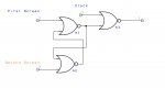
Well the bike too a little longer than planned. I had a good look though various types of flip flops and tried a few based around NAND and NOR gates. the only that came close was the SR latch but the SR latch with clock wasn't doing the trick really, so I made some changes.
this seems to work perfectly with the one exception that there is a chance that it may activate the set side of the latch meaning it lets the clock signal strait through. this can be resolved with the use of the clock generator send a signal to the reset side before anything else happens.
I haven't tested this beyond some mechanical switches to simulate the screens and the clock. I will try and get some code written to generate a 100k pwm from the 20x2 (for testing only at this point as I don't have a 08m2) and a counter on the 28x2 - my only concern at this point is the count command hanging around while the 28x2 should be sending commands of to the FPU - I was thinking maybe using the second line (a.1) to interrupt but don't know what affect this will have on the count command or weather the system will go back to counting on return.
Attachments
-
 72.9 KB Views: 6
so essentially the same but with active low, I will run some tests in the coming days. however some testing with the current nor gate seems to show that the reset signal isn't needed, after more than a dozen on/offs the same signal is outputted. so its not going to be the issue initially thought
any ideas how to get out of the count command?
any ideas how to get out of the count command?
well I have tried using the count command which in it self is fine, however due to the fact that the, the system will be waiting for input and having the count command running during that way causes issues. If I interrupt its does nothing until the count command has finished the count duration (which would have to be long due to the waiting part) before it does anything
test code:
I had thought about putting the count into the interrupt but that leave no option of escaping from it.
I had a 20x2 generating a 1kHz (for testing, if use this or a similar route I will increase this greatly) signal fed into the SR latch I posted earlier. the interrupt was taken from the reset side so is high when the system starts, goes low when the first screen is activated and then high when the second screen is activated and the first screen is deactivated - it does not go high if the first screen stays active - handy if you are using large size projectiles.
I will try and do some more testing with it but it seems a little redundant to continue following this path.
test code:
Code:
[color=Navy]#terminal 9600
      [/color][color=Blue]pause [/color][color=Navy]1000[/color]
[color=Black]init:
      [/color][color=Blue]let [/color][color=Purple]adcsetup [/color][color=DarkCyan]= [/color][color=Navy]%0000000000000010
      [/color][color=Blue]compsetup [/color][color=Navy]%0001010011[/color][color=Black], [/color][color=Navy]%10000110
      [/color][color=Blue]setintflags [/color][color=Navy]%00010000[/color][color=Black], [/color][color=Navy]%000100000[/color]

[color=Black]main:
      [/color][color=Blue]sertxd ([/color][color=Red]"Count start"[/color][color=Black],[/color][color=Navy]13[/color][color=Black],[/color][color=Navy]10[/color][color=Blue])
      count a.0[/color][color=Black], [/color][color=Navy]2000[/color][color=Black], [/color][color=Purple]w0
      [/color][color=Blue]sertxd ([/color][color=Red]"Count done"[/color][color=Black],[/color][color=Navy]13[/color][color=Black],[/color][color=Navy]10[/color][color=Blue])
      goto [/color][color=Black]main
      [/color]
[color=Blue]interrupt:
            setintflags off
            sertxd ([/color][color=Black]#[/color][color=Purple]w0[/color][color=Black],[/color][color=Navy]13[/color][color=Black],[/color][color=Navy]10[/color][color=Blue])
            [/color][color=Purple]flags [/color][color=DarkCyan]= [/color][color=Navy]0
            [/color][color=Green]'pause 1000
            [/color][color=Blue]setintflags [/color][color=Navy]%00010000[/color][color=Black], [/color][color=Navy]%00010000
            [/color][color=Blue]return[/color]
I had a 20x2 generating a 1kHz (for testing, if use this or a similar route I will increase this greatly) signal fed into the SR latch I posted earlier. the interrupt was taken from the reset side so is high when the system starts, goes low when the first screen is activated and then high when the second screen is activated and the first screen is deactivated - it does not go high if the first screen stays active - handy if you are using large size projectiles.
I will try and do some more testing with it but it seems a little redundant to continue following this path.
Can someone enlighten me, I am sure I am missing something or a lack of knowledge is blinding me (I hvae never used the SFR and couldn't seem to find a list of its register and what they did).
I have been looking at hippys timer code, and have run it on hardware, however I can not see how the picaxe detects the button push, my current assumption is reading data on the SFR (feeding back to the to pin 2/serial) and checking against previous reading - if so I could replace the button with a simple opto-isolator. If this is the case the chronograph will either need a dedicated connection on the current system (and moving some other stuff around) or be made to be standalone and send pulses when the projectile is arriving and allowing and extra delay to be added by the current controller.
I will have to do some work on the maths side of things and figure out the best way to send and correct the data that the FPU need for distance/time calculation buts that neither here nor there really as the raw data can be shipped in and divided by however much and added together (eg µs / 1000000, ms / 1000 and added together to get the true number to be dealt with)
That is correct, pushing the button simply closes the electrical path to allow clock pulses in to the internal counter.I have been looking at hippys timer code, and have run it on hardware, however I can not see how the picaxe detects the button push, my current assumption is reading data on the SFR (feeding back to the to pin 2/serial) and checking against previous reading
When the counter has been cleared and remains at zero the button has not yet been pushed.
When the counter is no longer zero the button has been pushed.
While a counter reading is not the same as the previous reading then the button is still being held.
Once a counter reading is the same as the previous reading the button has been released.
The button is in series between clock source and counter input. That could be replaced by a logic AND gate which passes the clock pulses or doesn't. You could possibly use an opto-isolator but not sure how you were planning on doing that.if so I could replace the button with a simple opto-isolator.
Some PICmicro internal timers are gated, have two inputs ( clock, enable ) and in internal AND gate so that might help in your case but you would have to read the PICmicro and PICAXE datasheets to see if they were available accessible.
ok thanks hippy, I hadn't thought of using a AND. as for the opto, I was going to have the input side connected to the conditioned signal from the screen allow the PWM to pass thought the other side and then stopping it when it goes low.
other signals to the standard input are in analogue normally, I have some Schmitt NAND gates here which will tolerate the analogue signals, and I need and inverter for programming the functions to the FPU. So I could use that to build the inverter I need, and deal with the signal, I may need to invert the signal too, but there should be enough NANDs to go around.
one last question - will the timer function on a 28x2 with changes to thing like em_64 instead of m_64.
I can't see any reason why it wouldn't.one last question - will the timer function on a 28x2 with changes to thing like em_64 instead of m_64.
I just tested the timer on a 28x2 and I didn't a anything when the button pressed and then released. I had to run at m16 due to the lack of a spare resonator - I will endeavour to test it at em64. I tried PWM signals from both b.5 and c.2 to pin 6. I may have missed something along the way but pretty I haven't.
Had a quick look at the data sheets and the addresses for the SFR seem to match between each chip
Edit:
OK I have found why it doesn't work on the 28x2, TMR1 on the PIC18Fxx2 Chips is an oscillator, I will have a look at moving over to TMR2 tomorrow as I have to get some sleep. it should just be case of changing the symbols to reference tmr2 instead of tmr1.
Any thought on this?
Last edited:
Timer 1 is what I believe you need to use and Timer 3 and 5 might also be usable. Timer 2 ( 4 and 6 ) can only take their clock source from the internal oscillator, are only 8-bit counters, don't allow any hardware controlled gating so are not usable in the same way.OK I have found why it doesn't work on the 28x2, TMR1 on the PIC18Fxx2 Chips is an oscillator, I will have a look at moving over to TMR2 tomorrow as I have to get some sleep. it should just be case of changing the symbols to reference tmr2 instead of tmr1.
Any thought on this?
Timer 1 hardware on a 20X2 is different from Timer 1 on a 28X2 so there will be some differences in SFR use, SFR configuration and different I/O connections and I doubt you can take the 20X2 code and just change the #PICAXE directives to get it to work on a 28X2.
I have been testing with hippys' timer, attempting to see if it will work on a 28x2 so that can integrated directly with the current flash controller (ie add the timer unit and FPU and write some new code for the system).Sorry, I've lost track on your current setup.
However I have been leaning towards building a standalone system that simply send a high signal out when the object arrives at the desired location. any additional delay can then be added with the flash controller.
I will have to order a display and some switches in the coming days, and on my 2 nights off I will get the screens built.
I will chuck together a breadboard circuit to test some ideas and report back later (maybe tomorrow after work).
Hippy I will try and find out what I need to replicate you timer on a 28x2 but its not a high priority at the minute - full integration into a single system can be done at a later date.