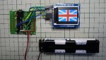
After Christmas I ordered via ebay a list of chinese made goodies no-one thought to give me as a present. One item was this full colour pixel display from hittime priced only £2.68 inc post and arriving within a fortnight. It is sold for the Arduino and has downloadable library files but not much real info on operation.
It took a while to break into its workings but it can be interfaced easily to a Picaxe. Of course running Basic on the chip means it runs slower by maybe three orders of magnitude than operating with precompiled code. So educational mainly but there will be applications if the limitations are understood.
I used the row of 16 plated through holes for connection but the yellow terminal pins seem to replicate the TFT pins (but not the SD). Wired to a 20X2 like this:
B.4 pin 14 - TFT CS pin 10 (CE) this signal taken low during SPI sending
B.7 pin 11 - TFT SCK pin 9 (SCK) use with hspisetup
C.1 pin 9 - TFT SDA pin 8 (MOSI) use with hspiout
B.6 pin 12 - TFT RS pin 7 (Cmd/Data) take high for data, low for a command
C.2 pin 8 - TFT RST pin 6 (Reset) pulse low only if needed. Power up will leave RAM a coloured mush.
B.3 pin 15 - TFT BL pin 4 (LED) take high for the backlight LED to turn on.
The real issue is what sequence of commands to wake up the display. Google the pdf for the Sitronix ST7735R control chip because this is required reading. Begin with SLPOUT and DISPON. Then RAMWR to start sending data and any following characters should hit the screen.
The display has 160 x 180 pixels, each with 3 bytes for colour so to fill it will need around 62 thousand bytes sent via SPI. Perhaps 24 seconds to clear to one colour (no hardware instruction) and the pixel writing demo attached takes around 50 seconds.
A feature to understand is the writing window – a rectangular area which can be set with x,y start and x,y end coordinates. Within that block the RAM is written in raster fashion but the direction can be changed by the MADCTL command. Dr Sheldon Cooper may appreciate the fun you can have with the example code.
I have also coded a character display of 18 x 16 lines which I hope to post shortly.
Attachments
-
 37.7 KB Views: 136
 -
10.5 KB Views: 34