PICAXE 08M2 Drawing way more current then normal

notzippy

New Member
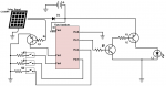
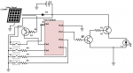
So I tried my pixaxe 08M2 in what I thought was a safe circuit, I tested the programming everything seemed to work fine, it controlled a solar light, the leds were driven through a pair of transistors from output c.0, it shut off after 4 hours and I checked the batteries, all seemed well. The next day the batteries were dead. I recharged and tested again, everything seemed to work fine. All switches worked all programming worked. So I checked the current. In standby the 08M2 was drawing 88ma, I tried a new one on the developer board with my software it drew only 0.6 ma, so I figured it must be the circuit so I pulled the processor out and put it in the developer board. It continued to draw 88ma, but still was operational. Any ideas on what could have happened ? The only output pin is current limited using a 100K resistor. The inputs are configured with pullups like

Code:
         let dirs = %00000001	; Assign c.0 as output all others are inputs
	; Specify pull ups
	pullup %011110

thx
Nz
 

erco

Senior Member
You need to supply lots more info if you want help. Schematic, photos and full code.
 

premelec

Senior Member
ANY floating inputs could produce this with nearby noise pickup - the pullups are weak - as erco says... supply details.
 

notzippy

New Member
Here is a rough sketch of the cct here http://www.picaxeforum.co.uk/showthread.php?26947-08m2-lookalike-solar-lights&p=276884&viewfull=1#post276884 , resistors are 100K . I measured the current draw to the processor with the LED's on vs off and it is less then 90 ua difference between the two

Code:
#picaxe 08m2

symbol LED = c.0
symbol LED_4hr = pinc.2
symbol LED_6hr = pinc.1
symbol LED_auto = pinc.4
symbol SOLAR = pinc.3 ; c.3
symbol ON_UNTIL = w0 ; b1:b0
symbol READ_VOLTS = w1 ; b3:b2
symbol CALC_VOLTS = w2 ; b5:b4
;symbol UNIT_STATUS = b0 ; bit0 LED status, bit1 solar status, bit2 startup , bit3 cycle
symbol LED_STATUS = b6
symbol BATTERY_LOCK_STATUS = b7
symbol SOLAR_STATUS = b8
symbol STARTUP_STATUS = b9
symbol CYCLE_STATUS = b10
symbol AUTO_ON = b11

symbol TRUE_CASE = b12
symbol SOLAR_ON = b13
symbol SWITCH_ON = b14
symbol INDICATE = b15
symbol LIGHT_DEBOUNCE = b16
symbol X = b17
symbol LIGHT_DEBOUNCE_MAX_TIME_OFF = 60 ; Max time to debounce solar is on and powering
symbol LIGHT_DEBOUNCE_MAX_TIME_ON = 60 ; Max time to debounce solar is off, and panel should be on
symbol TIME_MULTIMPLIER = 60 * 60 ; 60 * 60 multiplier to bring up times to an hour
symbol SECOND_MULTIMPLIER = 1000;7 ; 60 * 60 multiplier to bring up times to an hour
symbol LOW_VOLTAGE_OFF = 280 ; voltage to turn off
symbol HIGH_VOLTAGE_ON = 330 ; voltage to turn off


let dirs = %00000001	; Assign c.0 as output all others are inputs

main:
	; Specify pull ups
	pullup %011110
	;setfreq k31
	disablebod
	let SOLAR_ON = 0
	let SWITCH_ON = 0
	let LED_STATUS = 0
	let SOLAR_STATUS = 0
	let STARTUP_STATUS = 1
	let CYCLE_STATUS = 0
	let BATTERY_LOCK_STATUS = 0
	let LIGHT_DEBOUNCE = 0
shortloop:
	
      ; Fetch CV voltage into READ_VOLTS
      CalibAdc10 READ_VOLTS 
      ; CALC_VOLTS is voltage in centi-volts
      CALC_VOLTS = 55680 / READ_VOLTS * 2 
	debug
	if CALC_VOLTS<HIGH_VOLTAGE_ON then 
		BATTERY_LOCK_STATUS = 1
		let STARTUP_STATUS = 0
		goto mainloop
	endif
	sleep 2 ; sleep for 2.3 * 2 seconds
	gosub SET_CONFIG ; Initialize configuration
	if SOLAR!=SOLAR_ON then
		gosub turnon ; turnon if initiated when dark
	endif

	let STARTUP_STATUS = 0
	;sleep 10
	goto mainloop

mainloop:
	DO
	    ; Wait a second before processing further actions
          pause SECOND_MULTIMPLIER
	    
	    ; Fetch CV voltage into READ_VOLTS
	    CalibAdc10 READ_VOLTS 
	    ; CALC_VOLTS is voltage in centi-volts 55680
	    ; CALC_VOLTS = 52378 / READ_VOLTS * 2 +40
	    CALC_VOLTS = 55680 / READ_VOLTS * 2 
	    SOLAR_STATUS = SOLAR
          ; debug
	    
	    ; Check if battery is locked, caused by low voltage, if so
	    ; display will remain dark until battery are charged
	    if BATTERY_LOCK_STATUS=1 then
		;debug
		; check to see if charging, and the battery has a bit of a charge to it, if so unlock the battery
		; The reason for the .7 v difference is because the battery will bounce back a bit when the led are turned off
		if SOLAR=SOLAR_ON and CALC_VOLTS>HIGH_VOLTAGE_ON THEN
			let BATTERY_LOCK_STATUS = 0
			let indicate = 1
			gosub GO_INDICATE ; single flash indicating battery unlocked
			let LIGHT_DEBOUNCE = 0
			sleep 1;
			;debug
		else
		   sleep 300 ; ~2.3 seconds *300 Sleep for another 10 minuites until a charge begins to happen.
       		;debug
		ENDIF
	    ; Check to see if battery is low to prevent over draining battery
	    elseif CALC_VOLTS<LOW_VOLTAGE_OFF then ; Power should be good for processor until falls below 23 volts
		    ; turn off the leds and go to sleep for at least 10 minuites allowing batteries to recharge
		    ; and prevent over draining battery, lock state till charger is on again
      	   let BATTERY_LOCK_STATUS = 1
		   gosub turnoff
		   sleep 300 ; ~2.3 seconds *300, deep sleep 
	    else
		;debug
		; Normal cycle, if led is on or off we either check the on status or the off status		    
		if LED_STATUS = 1 then
			gosub CHECK_ON_STATUS
		else
			gosub CHECK_OFF_STATUS
		endif
		;debug
	    ENDIF
	;debug
    
	LOOP 
	end
CHECK_ON_STATUS:
	; While on the first step should be to check to see it should turn off
	if SOLAR=SOLAR_ON THEN
		; Check if solar is on for at least LIGHT_DEBOUNCE_MAX_TIME_OFF seconds (5 calls to this)
		if LIGHT_DEBOUNCE <LIGHT_DEBOUNCE_MAX_TIME_OFF then
			LIGHT_DEBOUNCE = LIGHT_DEBOUNCE + 1
		else 
			CYCLE_STATUS = 0 ; reset cycle counter
			; turn off led and return
			gosub turnoff
			return
		endif
	else
		; If we made it this far reassign the light debounce to 0
		LIGHT_DEBOUNCE = 0
	endif
	; No solar, check to see if timeout should occur yet
	if AUTO_ON!=1 THEN
		let ON_UNTIL = ON_UNTIL - 1
		if ON_UNTIL<1 then
			let CYCLE_STATUS=1
			let ON_UNTIL = 0
			gosub turnoff
			return
		endif
	endif
	return


CHECK_OFF_STATUS:
	; If we have completed a cycle defer checking until solar status is reset
	if CYCLE_STATUS = 1 THEN
		; Check that the light is on and geing charged
		if SOLAR=SOLAR_ON THEN 
			; Debounce the cycle change
			if LIGHT_DEBOUNCE <LIGHT_DEBOUNCE_MAX_TIME_OFF then
				LIGHT_DEBOUNCE = LIGHT_DEBOUNCE + 1
			else 
				let CYCLE_STATUS = 0
				LIGHT_DEBOUNCE = 0
			endif
		else 
			; Reset the light debounce 
			LIGHT_DEBOUNCE = 0
		endif
		return
	endif
	if SOLAR!=SOLAR_ON THEN ; Dark and not on the cycle
		if LIGHT_DEBOUNCE <LIGHT_DEBOUNCE_MAX_TIME_ON then
			LIGHT_DEBOUNCE = LIGHT_DEBOUNCE + 1
		else 
			gosub SET_CONFIG   ; Set the configuration for the loops or auto 
			gosub turnon;
		endif
	else 
		LIGHT_DEBOUNCE = 0 ; reset light debounce if off and solar is back on
	endif
	return

; Check the configuration settings to properly initialize turning on the led	
SET_CONFIG:
	let CYCLE_STATUS = 0 ; reset cycle
	let indicate = 2
	AUTO_ON = 1					; Default auto to on
	if LED_AUTO != SWITCH_ON THEN
		let ON_UNTIL = 0
		if LED_4hr = SWITCH_ON THEN
			let ON_UNTIL = 4 * TIME_MULTIMPLIER
			let indicate = 4
		END IF
		if LED_6hr = SWITCH_ON THEN
			let ON_UNTIL = 6 * TIME_MULTIMPLIER
			let indicate = 6
		END IF
		if on_until != 0 then
			AUTO_ON = 0
		endif			
	else
		let indicate = 3
	
	ENDIF

	IF STARTUP_STATUS = 1 THEN
		gosub GO_INDICATE
	endif
		
	return 
GO_INDICATE:
	; Flash indicator based on config
	for x=1 to indicate
		gosub turnon
		pause 500;SECOND_MULTIMPLIER/2
		gosub turnoff
		pause 200;SECOND_MULTIMPLIER/4
	next x
	pause 1;SECOND_MULTIMPLIER/8
	return
turnon:
	high LED
	LED_STATUS = 1
	return
turnoff:
	low LED
	LED_STATUS = 0
	let LIGHT_DEBOUNCE = 0
	return
 

premelec

Senior Member
It appears from what you say that your PICAXE got partially fried... I can't make out from your picture just what you have going - however I know from testing solar light units that they can put out way over 5 volts when unloaded so if in any way you have the regular solar light step up voltage into the PICAXE when unloaded that could blow something - please draw a complete circuit of the PICAXE and Solar light unit you are trying to control... or guard any inputs to your PICAXE much better and hope another one doesn't become defective...
 

notzippy

New Member
Attached better picture of cct, solar battery is always loaded across batteries, can the issue be powering up the ic ? The switch to turn it on / set the inputs is one ganged switch so the ic could get turned on and off and on again really quickly.

Solar.png
 

erco

Senior Member
You have 4 potentially floating inputs there, depending on switch settings and sunlight level. Per premelec, that's bad.

You're using your battery as a buffer/voltage limiter to keep Vin under 5.5V (what type of battery?). That's probably OK if your solar panel is small, but if it's big it could potentially cause damage.

Also, you are just draining your battery down to zero. Not good for long battery life. If you can spare a pin or two (or change to a bigger chip), you could use an ADC to monitor battery and solar panel voltage and disconnect your battery if the voltage gets too high or low. I'm a fan of small latching relays for low-power apps like this. Zero voltage drop, zero power loss except when switching. You could eliminate the diode (and its voltage drop)between your solar cell and battery and gain a bit of charging power.
 
Last edited:

notzippy

New Member
You have 4 potentially floating inputs there, depending on switch settings and sunlight level. Per premelec, that's bad.

You're using your battery as a buffer/voltage limiter to keep Vin under 5.5V (what type of battery?). That's probably OK if your solar panel is small, but if it's big it could potentially cause damage.

Also, you are just draining your battery down to zero. Not good for long battery life. If you can spare 2 pins (or change to a bigger chip), you could use an ADC to monitor battery and solar panel voltage and switch things on accordingly. I'm a fan of small latching relays for low-power connections. Zero voltage drop, zero power loss except when switching.
The solar collector is 10" x 2" , batteries are 3x 1.2v ni-mh 2000mah, the most voltage I have seen across thebatteries is 4.2, but you are right it could be better protected. The floating pins are programmed to be pullups, so should that not protect the inputs ? The input voltage is monitored in code, anything below 2.8v and the LED's turn off (and they wait for a voltage of 3.3 before allowing them to turn on again), if the unit draws only less than .1ma then there should be enough juice to keep it going until light.

What I am concerned about is the powering on / selector of the chip, it is a slide switch like this
2_pole_4_position_dip_slide_switch.jpg

A better interpretation of the cct would be here, but all the switches are ganged together.
Solar (1).png

So when it is turned on to a particular spot the picaxe will get turned on and off repeatedly. Could this cause issues ??

nz
 

AllyCat

Senior Member
Hi,

I doubt if the switch is the problem*. If you now have a PICaxe which continuously draws over 80 mA (in the circuit shown), that suggests that it has been damaged by over-voltage. The panel could easily deliver an excessive voltage, so you are relying on the batteries acting as a voltage regulator. That might be alright if they are always connected, but you can really only be sure if they're wire-ended and soldered into a PCB.

Much of what you have done seems reasonably correct, but I do have a few suggestions:

Personally, I would omit Q1 and Q3: 1k directly from Leg 7 to the base of Q2 could be fine (but the pin is then "active low") or put the LED in the collector of an NPN. However, there should be a resistor in series with the LED if the supply rail is 3 x NiMH cells (maybe it can be omitted if using a single LiFePO4 cell). And I hope you actually have a pull down resistor on Leg 2 and a decoupling capacitor across Legs 1 and 8 !

Others may disagree, but I'd just use a high value resistor (tens of kohms) from the panel to Leg 3. Ideally, with a Schottky diode (lower voltage drop) between the panel and battery.

I haven't looked through all of your program code, which already looks rather (over-)complicated, but I would arrange the LED also to be turned on (at any time) if the battery voltage rises above (say) 4 volts, to avoid overcharging.

*EDIT: I've just seen that you're (now) connecting the supply rail through the switch. I wouldn't do that (at least without thoroughly considering all the implications of make-before-break or break-before-make contact types, etc.).

Cheers, Alan.
 

notzippy

New Member
*EDIT: I've just seen that you're (now) connecting the supply rail through the switch. I wouldn't do that (at least without thoroughly considering all the implications of make-before-break or break-before-make contact types, etc.).
Thanks for the response, the cct / switch is not my own, this is an existing product that was defective, which I tried to fix in a minimalistic way (yes I got a little crazy with the programming, it is what I do..) the switch is very cheap with dead spots between each, so I will add a seperate switch to avoid the staggered start, I will also add in the high voltage protection in the code. and shop for a Schottky as well...
 

premelec

Senior Member
@notzippy.... so many details! Note that a pullup resistor is NO protection from input over voltage & current. Best put a 10K resistor in series with each input in play and actively limit the voltage on the PICAXE [they are a lot cheaper than PICAXEs]. Take a look at the PV open circuit voltage and note that it might be able to overcharge the battery - often in low power PV you can remedy this with a shunt regulator which diverts current at a particular voltage [the TL431 is a cheap and effective device of limited power capability but combined with a PNP on a heat sink can dissipate many watts if necessary]. Alan's suggestions are good - it depends on how far you want to go with your fix and its reliability... best of luck! [BTW a PV panel is substantially a constant current device - electrons out for photons in so clamping it's voltage will not ordinarily result in any trouble - ]
 
Top