jensmith25
Senior Member
I have a 08M2 chip in a commercial PCB which I can't get my programme to download to. I bought two of the same boards and after I couldn't get the first one to work I soldered up the second PCB but it's not working either.
I've checked it's not the chip which I can programme on a different PCB no problem. I tried checking the various points with a multimeter and it's showing that power is being delivered to the switches and the IC socket. I've also checked with the continuity setting and can't find anything wrong.
I've tried programming the chip on a different board and then plugging it into this board to see if it will flash any of the LEDs but that doesn't work either.
I've also tried a hard reset several times and a different 08M2 chip.
I know the cable is fine as I've been able to download to two different PCBs today.
I'm now stumped and assume there's something fundamentally wrong with my PCB. If it was just one PCB I would think it was dodgy soldering but I was very careful with the second PCB so it must be something else.
Any ideas?
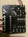
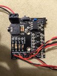
Photo attached.
I've checked it's not the chip which I can programme on a different PCB no problem. I tried checking the various points with a multimeter and it's showing that power is being delivered to the switches and the IC socket. I've also checked with the continuity setting and can't find anything wrong.
I've tried programming the chip on a different board and then plugging it into this board to see if it will flash any of the LEDs but that doesn't work either.
I've also tried a hard reset several times and a different 08M2 chip.
I know the cable is fine as I've been able to download to two different PCBs today.
I'm now stumped and assume there's something fundamentally wrong with my PCB. If it was just one PCB I would think it was dodgy soldering but I was very careful with the second PCB so it must be something else.
Any ideas?
Photo attached.