help with transistor

Goeytex

Senior Member
Hi Jim,

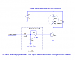
What I mean by a Poor Man's DAC is a PWM applied to a low pass filter so that a DC voltage is produced that is proportional to the PWM duty cycle.

The pros are that it is cheap ( 1 or 2 caps and 1 or 2 resistors) and is simple to implement.

The main cons are that there is scant little current at the output so that most of the time the DC signal needs to be buffered with an OPAMP, and that there can be some response delay. This delay can be made negligible by using a relatively high PWM frequency along with careful component selection.

Do a search here for "low pass filter" and see what pops up. I'm fairly sure that I and others have posted some diagrams here.
 

goom

Senior Member
It may be unnecessary to do any filtering. Certainly for brushed DC motors this is the case. Try with no filtering first. Just change the PWM duty cycle and see what happens. I would try a PWM frequency of around 1kHz to start with.
 

xtech007

Senior Member
Tried first option!

Hey all!
Got some work done!
Programed the 28x1 to output-4 high when switch is pressed. (4.96)
With the 430 ohm resistor at the base and 8.2mA passing from the picaxe collector reads 370-380 mA. Nothing is getting Warm or hot!
Here is a video;

http://youtu.be/oLFRZV7RLGA
 

Goeytex

Senior Member
Well Done and Nice Video

Now maybe test the Pump current with the motor under a load, meaning pump some water uphill at near maximum lift rating. Does the motor current increase significantly?
I would be doing all the tests from here on while pumping water.

There are 2 basic ways to use PWM.

1. Raw PWM to the motor where the current is alternately full on (MARK) and full off (SPACE)
The duty cycle determines motor speed.

2. The PWM is filtered to provide a DC Voltage proportional to the Mark/Space Ratio (Duty Cycle)
This will require adding some resistors and caps as well as a buffer (OPAMP) so that enough current is applied to the base of the transistor.

Number 1 is easiest to implement so try that first. User "Goom" suggested 500Hz to 3000Hz the PWM frequency so let's start with 500Hz and try that.
To use PWM, the Picaxe output Pin will need to be changed to "PWM 1" which is physical pin/leg 12 of the 28X1. This is the leg that will connect to the base resistor.

Attached is some code that you may find helpful. Each press of the button increases the duty cycle by 10 percent. However, be advised that the motor may not start until the duty cycle reaches a certain percentage. It also may be that the motor whines or makes a high pitched sound at certain duty cycle setting. And again a no load test will not necessarily indicate what happens when the motor is actually pumping water.

Code:
#Picaxe 28X1

 
Symbol DutyCycle = W0

[COLOR="#008000"]'PWM1 is physical Pin 12[/COLOR]
pwmout pwmdiv16, 1, 124, 0  [COLOR="#008000"]'// initialize PWM at 500Hz with duty at 0 - Motor is off 
[/COLOR]

[COLOR="#008000"]'// You will need to define the input pin for Button_Switch.  I used Pin7/Physical pin 18[/COLOR]
Symbol button_switch = Pin7 

Main:

    Do

        If Button_Switch = 1 then exit

    Loop  

    pause 50    [COLOR="#008000"] '// debounce[/COLOR]
    do while button_switch = 1   [COLOR="#008000"] '// wait for switch release[/COLOR]
    loop 

    DutyCycle = DutyCycle + 50    [COLOR="#008000"]'Increment duty cyckle by 10 percent with each button press[/COLOR]
                                 [COLOR="#008000"] 'When duty cycle reaches 100 percent the next button press [/COLOR]
       if DutyCycle > 500 then   [COLOR="#008000"] 'will turn the motor off [/COLOR]
           DutyCycle = 0
       endif  
    
    pwmduty 1,DutyCycle
     
    pause 1000    [COLOR="#008000"]'// Run at least 1 second[/COLOR]

goto main
 

westaust55

Moderator
Another experiment you can try is to drive the transistor a little harder and see if the transistor collector to emitter voltage Outage is reduced.

The transistor gain (Hfe) per your measurements is around 40 in the linear region.
Taking a transistor fully into saturation with can significantly reduce the Vce but the gain (Hfe(sat) ) (Hfe(eat) ) would drop to around 10 which means at least 40 mA into the base but the PICAXE can only deliver a recommends max of 20mA.
When a transistor is in saturation it does not turn off as fast so may not be ideal for high PWM switching frequencies.

The above said, measure the transistor Vce first with your 430 ohm resistor and then try again with a 330 ohm resistor which will increase the base current to around 12 mA.
If Vce does reduce that equates to less losses and heat from the transistor and more voltage available to the pump motor (with slightly higher current) and maybe slightly better water flow or water column head.
Keep in mind that many pumps have a square/quadratic curve) so a small change/increase in voltage may only give a very small increase in water flow.
 
Last edited:

AllyCat

Senior Member
Hi,

Westy's autospeller has been at work again! I think Outage = Voltage and eat = sat(uration). ;)

Note that if the power transistor is operating in switching mode (PWM) you must have a diode across the motor (to conduct the motor current back to the supply rail). I concur with starting at around 1 kHz or less.

It might be possible to get the "poor man's" (linear) circuit working without an Op-Amp. I'd try splitting the 430 ohms into two (say) 220 or 180 ohms in series, making a "T" filter with an electrolytic capacitor from the mid-point to ground. But use a much higher switching frequency, perhaps 20 - 50 kHz to keep the electrolytic to a reasonable size.

Cheers, Alan.
 

westaust55

Moderator
Thanks Alan. Fixed the iPhone auto correct "bugs".

With many commercial variable speed products the PWM carrier frequency is at the low end of the scale maybe 2 or 4 kHz and the upper end is 15 kHz and maybe higher these days.
At around 2 or 4 kHz there are reduced capacitive currents in the cable from VSD to motor but the motors can "cog" resulting in quite audible buzzing noise. At the higher frequencies little to no buzzing/cogging noise from the motors but increased capacitive currents which can be a significant percentage of VSD rated output resulting in need for output filters etc.

Even on the hobby scene, for model railways manufacturers of DCC decoders apparently used lower PWM frequencies but the locomotives were noisy and they increase the frequency to around 15 kHz and at least one European source using 23 kHz.
 

Goeytex

Senior Member
Hi,

It might be possible to get the "poor man's" (linear) circuit working without an Op-Amp. I'd try splitting the 430 ohms into two (say) 220 or 180 ohms in series, making a "T" filter with an electrolytic capacitor from the mid-point to ground. But use a much higher switching frequency, perhaps 20 - 50 kHz to keep the electrolytic to a reasonable size.
Cheers, Alan.
Yes, it might very well work.

I modeled it up in SPICE and it seem to work well with less than 4ma current ripple at the motor.load. Here is the diagram from Spice. The TIP31 Model may not be exact as the simulation shows a beta 100. So in the real world the 330ohm resistor may need to be reduced and /or the VR/POT may need to be changed to 500 Ohms instead of 1K.

The PWM freuqency was selected such that Duty ranges from 0-255 so that a POT connected to Picaxe ADC will provide a range of 0 -100 percent duty. It may need to be mapped so that the duty will be adjustable from perhaps 50 -100 percent as I doubt the motor will run well if at with a current of < 100ma.

Here's the schematic.
 

Attachments

xtech007

Senior Member
back on track again!

Hey fellas, my apologies for such a delay on results.
Had to finish a side project for the kids outsie the yard!
http://youtu.be/x9dHpS01QsE

Did try what Mr.Goeytex prescibed with code provided.
This are the results:
Reading at the base after the resistor
At 1st switch press .9v and .89 mA.
Collector 0v, 0 mA.
At 9th switch press 4.6v and 15.3 mA collector only then shows 12.1v at 397mA. Motor spins at full speed.
But nothing else before the 9th press.

No resisor at base just the pwm output from the 28x1:
At 1st switch press 1.2 v at .87mA
We can go all 10 switch press and read 5 v at base with max of 33mA.
But collector never reads any voltage.
 

premelec

Senior Member
Seems like you have a circuit problem - common V- supplies? Not sure what multiple presses do but looks like increase duty cycle - would help to have picture...
 
Top