help with transistor

xtech007

Senior Member
Happy Holidays!
Been playing around with transistor and the 28x1.
Followed manual or interfacing both!
Sucessfully worked lighting leds!
But soon realized It works as a switch.
Now after doing research find out this transistor are current driven!!

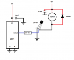
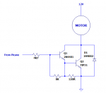
So, Got me couple of 2N4401 transistors (NPN) 600 mA max current.
Got the datasheet and got all info but I will like to understand it a little better.

How do I get the Base transistor Value? Using 5v at the base, 12v at collector, Load is 30 ohms , 400mA current 4.8 watt motor.

How do I get the proper hFE, Vce & Vbe from data sheet?

My math come up to 944 ohms.
Is that correct?
 

eggdweather

Senior Member
You have to select HFE based on collector current expected, so for your example that's about 400mA, they quote HFE=40 at 500mA, so use that.
The VBE value at a collector current of 400mA is about 0.75volts
Assume your using a 28X1 at 5volts, then base R is calculated thus:
V=IxR so R = V/I, when Ibase = 400mA/40 (collector current/HFE) = 10mA and potential difference is 5volts-0.75volts so V/I = 4.25/10mA = 425R nearest preferred value is 430R
OR
Rbase = (PicaxeSupplyVoltage - Vbase-emitter)/(CollectorCurrent/HFE)
 

xtech007

Senior Member
thnx guys!

Clears it up a little better!!
Read tons of ways of how people do the formulas, and all have different answers compared to mines!

This one matches! 430 ohms!
 

premelec

Senior Member
@erco - I wish they'd put the internal 'functional schematic' on that site - helps me to 'see' what's up... [and CMOS units have a lot different current and voltage specs still a cool part - though Don Lancaster declared it dead decades ago saying you could program a micro to do all that :) ]
 

john2051

New Member
Hi, looking at your requirements, and the specification of the transistor you are using I would guess its going to get warm.
Also you might have problems with it being an inductive load.
Personally, I would have used a transistor with a much higher current rating, or an fet with internal diodes, but I've had transistors fail at
less than specified currents, viz the 2N3055. These I believe were rated at 15Amps, yet I must have replaced hundreds of them in poorly
designed cb power supplies.
I don't know some of the others on this forum think.
regards john
 

xtech007

Senior Member
thank you all!

I had tought fet's can on drive voltage.
And used transistor so I could control speed of motor by controlling current.

By cotrolling voltage, I would think power would be lost. The motor simply would not work if it does not see 12 Volts.

Is there a better way?
I used the mentioned transistor becouse it was at hand and to gain knowledge of using them!

So far what I gain is how to calculate and read the datasheet thanks toyiu guys!
 

goom

Senior Member
The most common method of controlling DC brushed motors is by using Pulse Width Modulation (PWM). The motor is fed with the full voltage pulsed at a frequency typically 500 to 3000 Hz. The duty cycle of the pulses (on time to off time ratio) controls the motor speed. A FET is often used as the driver since their on resistance is low, and they can deliver very close to full supply voltage. A dedicated chip to drive the FET gate is often used to deliver the high instantaneous currents needed to quickly turn the FET fully on and off. A transistor drive can also be used, but will have a small voltage drop (around 0.6V) when fully on. Selecting an appropriate FET and driver is a whole new ball-game.
PWM can be very easily implemented using a Picaxe.
Motor speed can certainly be controlled by controlling current using a transistor. A couple of issues with this:
The transistor will act like a resistor, so will get hot in proportion to the voltage drop x current
The torque developed by the motor will reduce in proportion to current (PWM minimises this effect).

One easy way to implement DC (or even brushless) motor speed control is to use commonly available hobby type ESC's. They take standard hobby servo inputs (see SERVO and SERVOPOS commands), and output PWM to the motor. Some incorporate an H bridge which permits both foreword and reverse rotation.
 

xtech007

Senior Member
Great explanation!

Goom, great explanation regards driving DC motors with different options! Also including pwm and servopost to the mix. I have personally used MD03's as H-bridge to drive high current DC motors, they work with I2C, analog, PWM and high and low comands from a picaxe with great sults!

But like mentioned, Doing it for the learning curve and and fun!
By the way the dc motor I want to use is a brushless. Its a small water pump!
 

goom

Senior Member
Well, brushless DC motors are a different beast. Rather than using brushes to control the current through the motor windings, an external controller does the switching through 3 power input leads. I suspect that this would be quite difficult (maybe impossible) to accomplish with a Picaxe. There is a wide range of hobby ESC's available to take care of this, and easily controlled via SERVO and SERVOPOS commands.

If you are talking about a brushless AC motor, that is yet another beast. I'll leave it to others to comment on speed control of such a motor. I'm not even sure that it would be possible if it is of the type where speed is governed by synchronising with the AC supply frequency. More details of the motor would be required if you want some sensible comments.
 

xtech007

Senior Member
interesting!!

The motor Specs claim to be a brushless, but only have 2 leads.(Red & Black) Bought from ebay.
These are thespecs:
Features:
Brushless, permanent magnetic rotor.
Super long working life(more than 30000 hours).
Adopt high performance ceramic shaft.
The axis is enclosed with static sealing, not dynamic, which can avoid leaking problems.
Amphibious design.
Submersible installation and entirely waterproof.
low consumption.
low noise(less than35db).
Pump material: ABS.
Condition of use: continuously.
Fluids: Water, oil, gasoline, acid and alkali solution.
Working temperature: 0 ~ 75
 

Goeytex

Senior Member
The "motor" has an integrated driver much like a 2 wire DC brushless cooling fan motor. Thus only 2 external wires. These kind of motors can sometimes be controlled via PWM but may "protest" at certain PWM frequencies / duty cycles.
 

goom

Senior Member
So that indicates that it is may be an AC motor. What is printed on the motor? (Voltage, current/power, speed).

If it is in fact low voltage DC, try powering it with various voltages. That will determine whether it's speed can be controlled.
 

xtech007

Senior Member
sorry, Only half the specs showed.

Here is the other half:
Power consumption: 4.2W.
Rated voltage: 12V DC.
Max rated current: 350mA.
Max flow rate: 4L/MIN(1.06G/MIN).
Max Head(lift height): 3M.
Noise: <40dB(most 35dB).
Water proof class: IP68(can be submersible installed).
Life span: More than 30000hrs.
Power supply: Solar panel, DC electric source, battery
 

xtech007

Senior Member
Updates!

Finally! Kids asleep!
After soaking the kitchen and kids included, we're able to test the motor!
Test results:
With 12 Volts Dc connection stright to motor leads we get a tall stream of water flow ( about a foot tall) and we can hear the motor run fast!

Tried also Mr.Goom's suggestion.
@ 0-6 volts DC motor would not start.
@7 volts the motor turns and produces about 2 inches stream of water!
@8-12 the motor spins faster as voltage is increased and stream gets taller about 1-1/2 feet I would say.

Now adding the transistor in the mix:
Used the resistor mentioned 430 ohm in the base and 5v. 12v on the collector, tied the red lead to emitter and black lead to ground.

Nothing moves....
Tried a second transistor, same result.
After I dry up will have to get my meter and investigate.
 

Goeytex

Senior Member
Now adding the transistor in the mix:
Used the resistor mentioned 430 ohm in the base and 5v. 12v on the collector, tied the red lead to emitter and black lead to ground.
That will not work. The transistor is an NPN so you should connect the motor red lead to 12V, the motor black lead to the transistor collector and the transistor emitter to ground.
 

xtech007

Senior Member
I see!

Source instead of sink.
I take it my config would work only if transistor was used as a switch.

Goytex I tried your solution and no luck...
 

jims

Senior Member
xtech007...I've been following your thread; mainly out of curiosity. Looks as if you began by trying to understand how to use a transistor to turn the pump motor ON/OFF. This seems to have evolved to controlling the motor speed. Are you after pump motor ON/OFF?? pump motor speed control??? or to control the volume of water?
Just curious. JimS
 

Goeytex

Senior Member
Make sure that the transistor is oriented correctly and not blown. See Attached cartoon drawing.

Write your code so that the output is high for 5 seconds and low for 5 seconds, then measure the voltages at the output pin and at the base of the transistor. The output pin should switch between 0V and about 4.5V. The base should switch between 0V and about .7V. The motor should run for 5 seconds and stop for 5 seconds. This will determine if the transistor is working.

This motor may not be designed to be speed controlled from a variable current source and likely will not start at low current.
 

Attachments

Last edited:

xtech007

Senior Member
Jim, welcome!

I apologize, my Intentions were simple at first. Switching the motor ON- OFF.

Soon realize transistor are current amplifiers, so I figured lets try it!!!

Yes, H-bridges would do the trick, but
So would be Pulsing with Pwm and so forth, but would like to test this alternative!

My final goal is to control the height if the stream (by controling the pump).
Any other alternative is welcome!
Using transistors is preferable do to how sheap this buggers are.
 

AllyCat

Senior Member
Hi,

Source instead of sink.
I take it my config would work only if transistor was used as a switch.
No, it's because you wired the transistor as an "emitter follower" which has unity voltage gain, so the motor would not "see" more than about 4 volts (at best) from the PICaxe.

However, Goeytex's configuration should at least work (if you haven't mis-wired and/or destroyed the transistor), but probably not very well. The (minimum) current gain of the 2N4401 is 40 at 500 mA so the (nearly) 10 mA through the resistor should be just about enough. But that gain is specified with two volts across the collector-emitter, which means that the transistor could be dissipating one watt. The maximim rating for that transistor (without a heastsink) at "room teperature" is only 0.625 watt, so it might not work for very long!

That motor doesn't really look very suited to speed control, but perhaps something could be done with a PNP emitter follower (dissipating lots of power) or a PWM power supply configuration (requiring an additional inductor to maintain a dc voltage on the brushless driver circuit during the "flywheel", or energy recovery, phase).

Cheers, Alan.
 

Goeytex

Senior Member
Per the spec sheet the motor is rated at 12V/350ma. With a worst case gain of 40 you will need a minimum of about 8.75 ma of current at the base to just barely get to 350ma. However it may be a good idea to provide more current to assure that the transistor is fully on. The PIC/Picaxe does not lend itself to simple calculations for output pin current. The voltage always sags under a load and this affects current . All you can hope for is about 17 ma.

If the motor still does not run after testing with the example circuit, you can reduce the base resistor to as low as about 180 ohms. You can get a good idea of the base current by measuring the voltage at the I/O pin and using Ohms Law. For example, you measure the I/O Pin voltage to be 3.3 volts and you have a 330R resistor.

3.3 Volts Volts divided by 330 Ohms means there is about 10ma of current through the transistor base. You could then reduce the resistor to 220 ohms and measure and calculate again. Keep reducing the resistor value and recalculating until you get to 12 to 15 ma. I would not reduce the resistor to less than about 120 Ohms.

Alan is correct about the heat dissipation in the Transistor. It could get hot or even blow. This is why I suggested 5 seconds on and 5 seconds off. I have run a 2N2222 at 200 ma continuous (driving a brushless 12V computer fan motor) with no problems. However 350ma continuous through a 4401 without a heat sink is stretching the limits a bit. It it were me, I would use a FET instead of a transistor.
 

xtech007

Senior Member
Mr.Goeytex You are Right!

Blew my first transistor!
My wiring is just like you drew it.
After replacing transistor with new one the darn thing worked!!

Quickly realized the transistor got hot!
Maybe that's how the first one quit!

Test @ base with 430Ohm resistior:
Applying .8v motor starts slowly.
After that, the more Volts the faster the motor rev's all the way to 5v.
Also noticed at lower Volts the transistor takes longer to heat up.
Exp. @5v it gets hot within a sec.
@ 1v gets hot withing 3-4 sec.
 
Last edited:

xtech007

Senior Member
so far!

Well is past midnight here.
So far I have learned how to do the Calculations for the base resisor of an transistor, understand how to read the datasheet, and connections!

And now by experience how to take dissipation seriously!

Thank you guys for your help and time!
Ps: I could not resist to get my hands on a tip31 transistor also NPN with 3 Amp Ic max and 20W !
Will be testing that next!
 

MPep

Senior Member
I apologize, my Intentions were simple at first. Switching the motor ON- OFF.

Soon realize transistor are current amplifiers, so I figured lets try it!!!

Yes, H-bridges would do the trick, but
So would be Pulsing with Pwm and so forth, but would like to test this alternative!

My final goal is to control the height if the stream (by controlling the pump).
Any other alternative is welcome!
Using transistors is preferable do to how cheap this buggers are.
An H-Bridge is NOT the same as PWM control.
H-Bridge is to reverse the applied voltage.
You use a PWM switching transistor for speed control.
 

xtech007

Senior Member
MPep You are Right.

Pwm was mention here just as signal not actually compared to an H-bridge.

Now there are H-bridge that take pwm input for speed control but direction by a different signal.
 

Goeytex

Senior Member
Ps: I could not resist to get my hands on a tip31 transistor also NPN with 3 Amp Ic max and 20W !
Will be testing that next!
You may find that you have better results with a Darlington such as a TIP120. With a beta of 1000 the Picaxe will only need to supply about 500 microamps.

Or you can make you own Darlington with a 4401 and the TIP31. See attached for how.
 

Attachments

Last edited:

xtech007

Senior Member
Tip31 Results!

Morning Forum!
Got to test the Tip31, happy with results. It barely gets warm with full rpms, and just a bit warmer at the slowes rotation!

Also be know all this was done via analog, no picaxe was used. A potentiometer was used to produce the voltage at the base.

Next phase!!
How can I control the base via picaxe to control speed?
I would think PWM maybe servopost.
Any suggestions are welcome!
 

Goeytex

Senior Member
Well ....

You haven't given us very much other than you have not tested with a Picaxe.

What was the current through the base of the transistor with your analog setup?
...... At the slowes speed it would run?
...... When the motor just began to run at full speed?

What was the current through the motor at full speed ?
What size pot did you use?
What voltage was applied to the POT?
When your turned the pot what was the resistance when the motor just began to run at full speed (reached maximum current through the motor) ?

Did you take/log any voltage/resistance/current measurements at all?

Suggestions? Yes, ditch the pot and try it with a Picaxe I/O pin before you attempt PWM or anything else. Make sure you place at least a 120 ohm resistor between the Picaxe output and the base of the transistor. Does it run when the Picaxe pin is high? What is the motor current?
 

xtech007

Senior Member
Here we go!

Pot is a 5k, one leg tied to 5v the other to ground mid leg to a 430 ohm to base of the transistor. 10mA at 5v, @.8 volts motor starts slow. I would say transistor becomes saturated.

Motor red lead to 12v+, black lead
to collector, and emitter to ground. (Both 5 and 12v ground together)

Test:
@.8v at base, 80ma at colector
@ 2.5v at base 280 mA at collector
@ 4.8v at base 379 ma at collector.

I figured by using picaxe, a high out put would read 5v, apply that to the base resisor and motor would rev to full speed. Low output would turn motor off.
How can voltage of the output pin be changed?

Hope the info helps.
 

AllyCat

Senior Member
Hi,

emitter to ground.
......
@ 2.5v at base 280 mA at collector
@ 4.8v at base 379 ma at collector.
That shouldn't be possible with a normal bipolar NPN transistor ! Do you mean those voltages are at the top of the 430 ohm resistor? :confused:

Providing that you have a "flywheel" diode across the motor then you should be able to set up a suitable PICaxe pin to deliver PWM at a moderately low frequency (maybe 1 kHz). A "Servo" signal is NOT suitable because it will only give around a 10% duty cycle (mark-space ratio).

Cheers, Alan.
 

Goeytex

Senior Member
Allan beat me to it.

These are NOT voltages measured at the base of the transistor. They are the voltages measured at the wiper of the pot. In any case .....

Now Connect the Picaxe to the Transistor through the same 430 ohm resistor. For now, all the code needs to do is to make the pin high and keep it high.

Code:
High b.0
do
loop
Load the program and measure the voltage at the Picaxe Pin. What is it?
Measure the current through the motor. Is it about 379 ma? If not then what is it?
IF less than 379ma then reduce the resistor to 330 ohms. If still not ~379 ma then reduce the resistor to 220 ma.
(Didn't I already suggest this? Or am I having a deja vu?}

Let us know what happens. One we determine that the Picaxe can drive the transistor to saturation, you can move on to trying using PWMOUT or PWMOUT with a low pass filter ( Poor Man's DAC) for speed control.
 

xtech007

Senior Member
Will do!

Goeytex, you right again!
The voltage refered was from the wiper to the resistor to the base!

Guys, sorry for the wild explanation while excited to move on and low electrinic knowledge can only allow me to explain so far.

Soon I get home will post findings!

Thank you guys!
 

jims

Senior Member
Goeytex... What are the pros & cons of using a DAC ("Poor Man's DAC for speed control") for this DC motor speed control application. How would DAC control be implemented? Thank you, JimS
 
Top