Hi
Was hoping someone could help me out here, have some poorly programmed solar lights that I bought, they have a switch setting for staying on 4,6 hours or all night. The pinout is a dead ringer for 08m2, but the chip has no markings on it. The issue with the program is that when the switch setting is for 4 or 6 hours on they work fine the first night, but the second night they stay on dusk to dawn (The auto turn off after 4 hours is ignored).
So I bought a development kit for the 08m2, wrote a program and popped out the chip from the board and tried to reprogram it. No luck, did not respond to any commands. Which brings me to my three questions below.
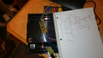
1) Any ideas what the chip could be ? Like I said the pinout is identical to the picaxe, pin 2 was open and pin 7 was the output with pins 3,4,5,6 used as inputs. The cheapest fix would be to reprogram this chip but I am not sure what it is (A clue may be in question 2 below)...
2) The inputs for the switches are pull downs (open switch resistor to ground). When I replaced the chip with a 08m2 picaxe it read these as 0 (off) even though the pins were open. The only way I could get them to read as 1 was to add a pull up resistor to the pin. Is there a way to program the picaxe to treat an open input pin as a 1 ? (I thought the inputs should have a pull-up resistor internally ??)
3) The programming software PixAxe editor 6.7.5 has a simulate mode with a "connect to real life pixaxe" option, but when I choose it I get a message saying it is disabled for this beta release of the software. Where can I find the non beta version of the software ? On the picaxe site it does not saying anything about the software being beta or not... (I tried downloading an older version of the logicator to try to connect to the chip but it failed saying the chip was not the correct version). The reason why I wanted to connect was to monitor the inputs, I tried the datalink as well but that did not seem to be working either and does the xbee wizard do anything beyond reading in at higher and higher baud rates ? Programming the chip in the editor was a breeze and it was nice to do a software simulation of the circuit but connecting to the live HW would be even better
thanks
Nz
Was hoping someone could help me out here, have some poorly programmed solar lights that I bought, they have a switch setting for staying on 4,6 hours or all night. The pinout is a dead ringer for 08m2, but the chip has no markings on it. The issue with the program is that when the switch setting is for 4 or 6 hours on they work fine the first night, but the second night they stay on dusk to dawn (The auto turn off after 4 hours is ignored).
So I bought a development kit for the 08m2, wrote a program and popped out the chip from the board and tried to reprogram it. No luck, did not respond to any commands. Which brings me to my three questions below.
1) Any ideas what the chip could be ? Like I said the pinout is identical to the picaxe, pin 2 was open and pin 7 was the output with pins 3,4,5,6 used as inputs. The cheapest fix would be to reprogram this chip but I am not sure what it is (A clue may be in question 2 below)...
2) The inputs for the switches are pull downs (open switch resistor to ground). When I replaced the chip with a 08m2 picaxe it read these as 0 (off) even though the pins were open. The only way I could get them to read as 1 was to add a pull up resistor to the pin. Is there a way to program the picaxe to treat an open input pin as a 1 ? (I thought the inputs should have a pull-up resistor internally ??)
3) The programming software PixAxe editor 6.7.5 has a simulate mode with a "connect to real life pixaxe" option, but when I choose it I get a message saying it is disabled for this beta release of the software. Where can I find the non beta version of the software ? On the picaxe site it does not saying anything about the software being beta or not... (I tried downloading an older version of the logicator to try to connect to the chip but it failed saying the chip was not the correct version). The reason why I wanted to connect was to monitor the inputs, I tried the datalink as well but that did not seem to be working either and does the xbee wizard do anything beyond reading in at higher and higher baud rates ? Programming the chip in the editor was a breeze and it was nice to do a software simulation of the circuit but connecting to the live HW would be even better
thanks
Nz
")