Hi all,
Excuse my newbieness in this, i'm just getting started in this whole electronics thing. I am building an automatic feeder for a friends farm to feed animals when they go on holiday. Essentially the electronics part is an alarm clock, I have a PICAXE 18 high power project board with L293D motor driver hooked up to a motor which operates the feeder.
The supply to the board (and motor) is 12V from a general everyday battery with a 5V 1A regulator to power the chip.
I also have a Serial OLED display with clock module installed.
What I would like to achieve is to have 2 alarms; say one at 8:00am and one at 16:00pm when the motor will activate until a microswitch is pressed when the feeder mechanism moves round to the "fed" position.
My code is as follows
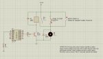
B.7 is the serial output to the OLED module and embedded alarm clock
C.7 is the serial input from the OLED module that goes high for 5 seconds when the alarm time is reached
B.4 and B.5 are motor outputs
C.0 is the microswitch intended to stop the motor
My problem is as follows: how can I implement the second alarm? Originally I was thinking when one alarm goes off, it cancels said alarm and reprograms the next time. Then when that time is reached, it cancels the alarm and reprograms it for the original time. Have some sort of variable (b0 in the code) that alternates?
Also I would like the motor to effectively "latch" once the alarm has gone off since the pin only remains high for 5 seconds.
The microswitch must return the whole circuit to the "waiting for next alarm input"
Apologies if anything is unclear, would appreciate some advice here!
Thanks,
Excuse my newbieness in this, i'm just getting started in this whole electronics thing. I am building an automatic feeder for a friends farm to feed animals when they go on holiday. Essentially the electronics part is an alarm clock, I have a PICAXE 18 high power project board with L293D motor driver hooked up to a motor which operates the feeder.
The supply to the board (and motor) is 12V from a general everyday battery with a 5V 1A regulator to power the chip.
I also have a Serial OLED display with clock module installed.
What I would like to achieve is to have 2 alarms; say one at 8:00am and one at 16:00pm when the motor will activate until a microswitch is pressed when the feeder mechanism moves round to the "fed" position.
My code is as follows
B.7 is the serial output to the OLED module and embedded alarm clock
C.7 is the serial input from the OLED module that goes high for 5 seconds when the alarm time is reached
B.4 and B.5 are motor outputs
C.0 is the microswitch intended to stop the motor
My problem is as follows: how can I implement the second alarm? Originally I was thinking when one alarm goes off, it cancels said alarm and reprograms the next time. Then when that time is reached, it cancels the alarm and reprograms it for the original time. Have some sort of variable (b0 in the code) that alternates?
Also I would like the motor to effectively "latch" once the alarm has gone off since the pin only remains high for 5 seconds.
The microswitch must return the whole circuit to the "waiting for next alarm input"
Apologies if anything is unclear, would appreciate some advice here!
Thanks,
Code:
start1:

init:
pause 500 'initialise display

serout B.7,N2400, (253,8,"00/00/00 08:00  ") 'set morning alarm time to 08:00
pause 500


main1:
serout B.7,N2400, (254,1) 'clear display to indicate that this code is running and the time is updating
pause 500
serout B.7,N2400, (1) 'display predefined message 1
pause 100
serout B.7,N2400, (0) ' display time
pause 4900
goto main1 'loop


start2:

main2:

let b0 = 1

if pinc.7 = 1 and b0 = 1 then gosub alarmam 'if variable b0 is 1 then morning alarm will activate
if pinc.7 = 1 and b0 = 2 then gosub alarmpm ' if variable b0 is 2 then afternoon alarm will activate

goto start2 'loop

	alarmam: 'morning alarm
 high b.4 'start motor
 low b.5

if pinc.0 = 1 then low b.4 'wait for alarm cancel switch then switch off motor
endif

goto start2

	alarmpm: 'afternoon alarm
high b.4
low b.5

if pinc.0 = 1 then low b.4 'wait for alarm cancel switch then switch off motor
endif

goto start2

end
Last edited by a moderator: