Infrared sensor not working

jensmith25

Senior Member
Hi,

I have used a RK Education low power board RKP14LP with the Picaxe 14M2 chip to set up remote control for some LEDs. I'm having problems though and I think it's the way the infrared sensor is connected into the board as it was quite difficult to work out what should go where.

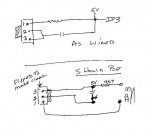
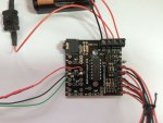
Pictures of the board and the board input pins.

IMG_0869.jpg

IMG_0871.jpg

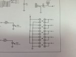
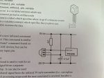
This is the link to the board schematic: http://rkeducation.co.uk/documents/instructions/RKP14lpinst.pdf

I'm using 4.5v power source. The red jumper wire on input 3 I have disconnected and it is still not working.

The 4k7 ohm resistor is wired into the red wire.

The 4.7uf capacitor is wired where the resistor would normally go.

I've used the code example from manual 2 for the irin command so that should be ok.

Any ideas what I've done wrong?

Jennifer,
 

Reloadron

Senior Member
OK, what IR sensor are you using? Do you have a link? I see your jumper on IP3, why is that there? The inputs are designed to form dividers. If you look at the example in the data sheet using a LDR they use a 1K Ohm resistor in series with the LDR to form a divider network. So you are using a 4K7 resistor rather than a 1K? I see the lump in the orange wire. :) What is needed is the data sheet for the IR sensor you are using. That would be a start anyway.

Ron
 

stevesmythe

Senior Member
I think you have wired things incorrectly. The 4k7 resistor should go between the signal and V+ while the capacitor should go between V+ and 0V.
 

Reloadron

Senior Member
OK, what you have is an actual Infrared Sensor Module. Now per post #4 this isn't quite an LDR where we would use a divider so yes, your 4,700 ohm resistor needs to go. The module has a +V (power), Ground and a signal output. While I am thinking about it, these modules that respond to IR can be sensitive to ambient room lighting.

Descriptions
The device is a miniature type infrared remote control system
receiver which has been developed and designed by utilizing
the most updated IC technology. The PIN diode and
preamplifier are assembled on lead frame, the epoxy package is
designed as an IR filter. The demodulated output signal can
directly be decoded by a microprocessor
.
So in this case the output can be directly coupled to a microprocessor. The module takes care of demodulating the signal. You can try using a remote control for a TV or DVD to get some signals to play around with (pulse trains). Read the data sheet for the module. As mentioned, the 47uF cap goes across Vcc and ground as close to the power and ground pins as possible. The output goes to your microprocessor or micro-controller and will be pulse trains depending on your IR source. Keep in mind Jenn, this is nothing like a traditional LDR (Light Dependent Resistor).

Also, if you want to use a pull up resistor I would place a 10K resistor between the module output and Vcc.

Ron
 

jensmith25

Senior Member
The Picaxe circuit creator specifically tells you to use the 4k7 ohm resistor as per the bill of materials and also the circuit diagram. That's why I bought everything because their remote control handset and the IR sensor are all specified together.

This is the circuit diagram
IMG_0872.jpg
 

stevesmythe

Senior Member
By the way, if you're wanting to decode the IR signal using the Picaxe Basic IRIN command, it needs to be a Sony-protocol remote control.
 

hippy

Technical Support
Staff member
This is the circuit diagram
Note the order of pins on the IR sensor ...

1 Signal to PICAXE, with 4K7 pull-up to +V
2 0V
3 +V

Without knowing which colour wires you have connected to the sensor it's hard to tell if you have it right. Either way the 4K7 inline with your red wire seems to be wrong, as is connecting the cap across 0V and signal input.
 

RexLan

Senior Member
I think you have it wired incorrectly and the sensor may still be OK because the capacitor is blocking the voltage.

It looks like you have the resistor in series with the 5v going to the sensor instead of pulling the line high.

I reversed the IR module on the bottom to make the drawing clear.

The two holes on the right are both connected to Input 3.

The two holes on the left are:
top = 5v
bottom = 0v

Here is how I think it should be wired up.

Someone need to check this for me too !!
 

Attachments

jensmith25

Senior Member
Looking at the Picaxe circuit for the irin command, leg 1 should be connected to the resistor and 3 to the capacitor I think?
 

jensmith25

Senior Member
Mostly. What I couldn't grasp with the Picaxe circuit is how IR leg 3 could go to both the + and gnd at the same time, plus be linked to the capacitor as there didn't seem to be another gnd hole on the board as they were linked to pin 3.
 

hippy

Technical Support
Staff member
Someone need to check this for me too !!
Once I had twigged the components on the right are sitting in the four holes of the circuit board it made sense to me and looks to be correct, matches the diagram in the PICAXE manuals.
 

hippy

Technical Support
Staff member
Mostly. What I couldn't grasp with the Picaxe circuit is how IR leg 3 could go to both the + and gnd at the same time, plus be linked to the capacitor as there didn't seem to be another gnd hole on the board as they were linked to pin 3.
I think the confusion there is with crossing lines in the circuit in the PICAXE manual. Where lines cross they aren't electrically joined. Only where there are 'black blobs' do the wires electrically join.

So, as per the PICAXE Manual, the wire comes off leg 2 to the right, turns down, passes over the next horizontal wire, then joins to 0V only.

Leg 3 goes off to the positive end of the capacitor and 5V only.
 

RexLan

Senior Member
Mostly. What I couldn't grasp with the Picaxe circuit is how IR leg 3 could go to both the + and gnd at the same time, plus be linked to the capacitor as there didn't seem to be another gnd hole on the board as they were linked to pin 3.
First thing you need to work on is understanding the schematic.


The top left hole is +5v
The bottom hole on the left is 0v ground

The two holes on the right are BOTH connected to input 3

++++++++

The IR leg 3 only goes to +5v That is top hole on left.

The capacitor goes from +5v to 0v ground (bottom hole on left). It can get the +5v anyplace including from leg 3.

The 4K7 resistor goes from +5v to input 3 AND leg 3 of the IR part

Leg 2 goes to 0V ground ... bottom hole on the left.
 
Last edited:

jensmith25

Senior Member
I do understand what you've draw and what goes where. What I don't understand is that this diagram:IMG_0872.jpg shows the resister coming off leg 1 of the IR sensor does it not? You have it on leg 3?
 

RexLan

Senior Member
No, I do not. Hippy explained the confusion.

Leg 1 on my drawing goes to the to input 3 ... bottom right hole.

Leg 3 goes to +5v ... top left hole.

The resistor also goes to +5v (top left hole AND to input 3 ... top right hole.

Try hooking it up exactly as I drew it and see if it works ... let us know.

Also, be sure you have the capacitor installed correctly with the - side to ground.
 

jims

Senior Member
I do understand what you've draw and what goes where. What I don't understand is that this diagram:View attachment 17473 shows the resister coming off leg 1 of the IR sensor does it not? You have it on leg 3?
Is part of this confusion due to the way the circuit is shown on this drawing from the manual? The view showing the pins extending downward from the module shows pin #1 on the left when facing the "bubble"on the module. This is correct per the datasheet. The other view is actually as viewed from the top of the module (as if looking through the module from the top). The way that it is portrayed one would assume that it's a bottom view, and it is not. Jims
 

jensmith25

Senior Member
I will wire it up as shown tomorrow and I'm sure that will be correct. I think my confusion is entirely with the Picaxe diagram as I'm struggling to read it which is obvious given my mistakes with the circuit board wiring.
 

RexLan

Senior Member
Both views are correct but confusing. Just be sure you have the IR part correct and that pin 1 is correct. It is on the left with the bubble facing to the left as you said and on the left as you are looking at it.

Verify that all your other connections are correct, especially the battery +5v and ground (0v)
 

jensmith25

Senior Member
Thanks RexLan. That's really helpful.

I know the battery is correct and the other connections because the programme downloaded fine.

I'll report back when I've re-soldered it tomorrow. Hopefully with it working!
 

jensmith25

Senior Member
It's working

Just to let everyone know that the remote control and IR sensor are now working. Used the sample programme to switch 1 LED on and off and it's working fine.

Thanks everyone for your help.
 
Top