HABAXE2 - a LoRA based High Altitude Balloon Tracker Project

srnet

Senior Member
Version 2 of HABAXE will be using a RFM98 transceiver, this uses Semtechs new SX1278 LoRa device.

The device is similar in size and capability to the RFM22B. It can generate FSK RTTY too but the LoRa telemetry from the Semtech device has much greater range than the FSK data telemetry produced by the RFM22B.

A benefit of using data telemetry for tracking is that a receiver can be left running unattended as the receivers are fairly tolerant of frequency changes by the transmitter, unlike FSK RTTY which needs frequent manual re-tuning.

I have carried out range comparisons of the SX1278 device versus the RFM22B (Si4432 based) first on Tenby beach with Arduino based code, a series of 1km across town tests and eventually a 40km LOS test between two hilltops with PICAXE code. The LoRa devices show in all these tests between 17dB and 19dB of signal gain over the performance of the RFM22B when used at 1000bps (40km needed only 2mW !). Using the LoRa device at 100bps yields a further 10dB improvement. 17dB equates to 7 times further distance, 27db to 22 times further distance.

Now 2mW was the limit of reception at 40km, so you can conclude that the RX needed at least -114dBm of signal to reliably operate. However the LoRa calculator claims the sensitivity at the bandwidth and spreading factor was -131dBm, so where has the missing 17dBm gone ?

The sensitivity quoted is in reality a figure that cannot be used, at least not on Earth, the background noise level is too high. I checked and a typical background noise level reported by the SX1278 RSSI was -100dBm. Where the SX1278 device is getting its real world performance from is its ability to receive signals below the noise level. The signal to noise ratio for the spreading factor used in the 40km LOS test (8) is quoted as -10dBm, so the receiver should work if the signal was 10dB below the noise level. 10db below a noise level of around -100dBm is -110dBm, close to the signal level that 40km\2mw would have produced.

Putting the LOS test results into distances would produce for a power of 10mW a LOS range of;

1000bps – 90km
100bps – 280km

On simple ¼ wave wires !

The addition of a vertical gain antenna and\or LNA should improve on these distances.

If you are going to use LoRa data telemetry for HAB tracking you need a LoRa receiver. I had previously designed my own complete receiver boards using a PICAXE 28X2, but a suggestion by forum user MFB, provided a cheaper and simpler solution.

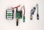
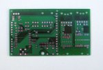
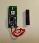
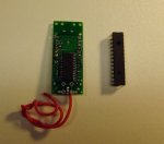
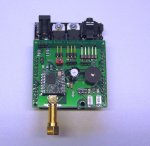
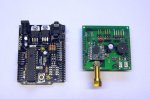
Rev Ed make the AXE401 Shield base, it uses a 28X2 and takes most standard Arduino shields. So the HABAXE2 Shield was born, see pictures. It's a simple PCB for the RFM98 about 50mm x 53mm and plugs into the AXE401 shield base or indeed an Arduino Uno if you must.

The shield can just be used as a data telemetry transceiver; all you need to fit is the RFM98, the pin headers and a bit of wire for an antenna.

There are also connectors for an external GPS, a serial LCD display and external buzzer. There are 2 LEDS, 2 Switches, a DS18B20* temperature sensor and an on board buzzer. So for larger HAB payloads the shield could, together with the AXE401, be used as a HAB tracker in its own right.

The shield can be used with a variety of GPS, although the software may need to be tweaked for different modules.

The shield does make playing with and testing different GPSs and the RFM98 quite easy, and it has enough I\0 to be used as a HAB tracker for larger payloads.

More updates and links to software later.
 

Attachments

Last edited:

srnet

Senior Member
The shield base works with a variety of GPSs.

Shown is the shield connected to a Ublox MAX8Q, also shown is a Mediatek 3329 and a Ublox MAX7 module from HAB supplies, all work. The MAX7 and MAX8 can be set to high altitude mode.

The MAX8 GPS starts in GNSS mode, which disables power saving. The data sheet is somewhat obscure in how you switch it across to power saving normal GPS mode. The HABAXE software does work if you change the program to look for GNGGA sentences instead of the more normal GPGGA. Some data sheet research required.

The PCB has layouts for Ublox Neo6 and Ublox Max GPS.
 

Attachments

srnet

Senior Member
I have been (slowly) working through the process of splitting the various programs for HABAXE into a set of programs that use the #INCLUDE facility of PE6, which at last seems stable enough to use.

The various programs, with symbol files for hardware and variables etc will be found on the HABAXE V2 LoRa Dropbox;

https://goo.gl/rBeCem

The programs are working, but there will be some changes as I ready the Pico tracker for a flight.

There is a report on the dropbox "LoRa Transceivers a Simple Approach to testing.PDF" which details the testing I have carried out to date.

There are a fair few referances to satellite operation in the report. If the RFM22B was good enough for $50SAT (which reaches its first birthday on Friday incidently) then the LoRa devices which are clearly so much better, will surley end up in orbit in the near future.
 
Last edited:

srnet

Senior Member
Generating UBLOX GPS Configuration Messages

Some of the configurations for the UBLOX GPS require the creation of PUBX (ASCII) or PBX (binary) configuration messages.

You can work these out from the manual, with some difficulty, but you then need to work out what the checksums are.

There is a tool provided by UBLOX that will do all this for you, its called U-Centre, runs under Windows, as of the time of writing the latest version is 8.12. I recommend you download and install it.

You can connect U-Centre it to a running GPS where you will be able to see all the information on satellites, signal strengths etc. You can also make configuration changes and test the effect.

The RFM98 shield has a connector on it to allows the serial connection to the GPS to be intercepted, you will need to make up a 3 pin 0.1" header lead (I used a servo lead) and connect a 3.5mm line socket wired for an AXE027 lead. You will also need to use the FTDI config utility to invert the polarity of the RX and TX away from normal PICAXE programming use. Myself I keep a AXE027 permanently set to invert mode. You will also need to fit the jumper on the shield that holds the PICAXE 28X2 in reset, otherwise it will conflict with the UBLOX GPS.

The document explaining how to use U-Centre is on the dropbox;

https://goo.gl/rBeCem
 
Last edited:

srnet

Senior Member
Pico Tracker - it even works

Just completed the assembly of the Pico version of the HABAXE V2 tracker.

The first version of HABAXE was based on the RFM22B, 40X2 and Ublox Neo 6 GPS, it weighed a porky 9.8g without battery.

This newer version is based on the RFM98, 28X2 and Ublox Max 8 GPS, it weighs 3.6g, without battery.

It uses the same basic hardware as the RFM98 shield version. You can develop and test the software on the larger much easier to use (and build!) platform, then use the same software to program the Pico version by selecting the appropriate hardware definitions file.
 

Attachments

srnet

Senior Member
Pico tracker is a bit lighter than I thought it would be, around 3.8g plus battery (Pictures above).

It uses the same code as the RFM98 shield version and the tracker Pico tracker has the addition of a watchdog, that resets the tracker if you don’t toggle an input pin every 90 seconds or so.

Having the shield use the same hardware as the Pico tracker is a winner, it’s just so much easier to develop and test on the larger platform.

With an 8g, 380mahr LiPo battery, for an AUW of 12g its been running for 24 hours, alternating between FSK RTTY, LoRa 100bps and LoRa 1000bps, 1 minute between transmissions. The GPS is in power save mode, left on all the time so the current consumption of the Ublox 8 in cyclic mode does seem to be very low.

For UK FSK RTTY use, the 380mahr battery will last long enough for most purposes, within 24 hours it will very likely be out of UK airspace anyway.
 

srnet

Senior Member
The 380mahr LiPo battery lasted a total of 34 hours.

By counting the number of transmissions, their length and current consumption, it was possible to work out the average current consumption of the GPS and PICAXE, this was 10.4mA, so the GPS is clearly a very low power consumption device.

The transmissions, FSK RTTY and LoRa data took about 20% of the total power, so if further power reductions are needed, then investigating the GPS operation is the place to start.
 

srnet

Senior Member
Finally worked out how the power saving on th UBLOX GPS works.

When it starts up it's in GLONASS mode, and for reasons I dont know, power saving does not operate in that mode. So the first thing you do is disable GLONASS mode;

hserout 0, ($B5, $62, $06, $3E, $0C, $00, $00, $00, $20, $01, $06, $08, $0E, $00, $00, $00, $01, $01, $8F, $B2)

Then you can enable power saving;

hserout 0, ($B5, $62, $06, $11, $02, $00, $08, $01, $22, $92)

When the GPS is aquiring its first fix, current consumption is around 28mA.

Once its aquired a fix AND the signals are strong enough it goes into power optimised tracking mode (POT).

In POT mode the GPS receiver is kept active but the current consumption drops to around 12ma.

In POT mode you can define how often it will get a new fix and sends out the configured seantances. It defaults to once a second and there is a very brief current pulse (above 12ma) as it gets the fix and sends the sentances out. In most cases you can leave the update period at 1 second, there does not appear to be much power saving if you extgend this period to 5 or 10 seconds.
 
Last edited:

srnet

Senior Member
HABAXE2 the Pico LoRa tracker is ready for launch, AUW around 14g with 24 hours of battery, balloon is a 36" foil.

Launch sometime over the Christmas break if the weather permitting. Flight predictions from the Shrewsbury area currently look good next Tuesday and Wednesday.

Transmissions are at 10mW. The tracker payload is in FSK RTTY and LoRa telemetry.

The FSK RTTY is USB, 100baud, 7bit, 2 stop bits, no parity. Frequency shift is 366Hz, transmit frequency Likely to be 434.400Mhz.

The LoRa payload is in two forms, the same FSK RTTY payload at BW41.7khz, SF8, CR4:5 (1042bps) and just the latitude, longitude and altitude at BW41.7khz, SF12, CR4:5 (98bps). The shorter LoRa payload is intended to be received and converted back into NMEA and mimic a GPS so the trackers path can be plotted with PC map application. This lower data rate LoRa should have a 10dB advantage over the 1042bps so should go around 3 times further.

There is handshaking between ground station (an RFM98 Shield) and the tracker which allows requests for telemetry tests (sent by the tracker) to be queued. These requests are sent on receipt of a ‘ready’ packet from the tracker when it enters listen mode. The tracker can be commanded to transmit a series of descending power packets in any LoRa mode, the ground station is used to receive these packets, this should assist in evaluating the performance of the various, bandwidths, spreading factors and coding rates.

Full Payload;
Tracker Identifier, HABAXE2
Sequence, position update number.
Time
Latitude, decimal degrees, minus (-) for West
Longitude, decimal degrees, minus (-) for South
Altitude, M
Speed, kmph
Track, degrees
SNR, Signal to noise ratio during last packet reception
RSSIP, RSSI of packet received
RSSI1, Noise level before packet received
Resets, Number of times tracker has reset (it has a watchdog)
BatterymV
Temperature, C
GPSlock, Y or N
Flags byte.

Short Payload;
Latitude, decimal degrees, minus (-) for West
Longitude, decimal degrees, minus (-) for South
Altitude in Metres
 
Last edited:

srnet

Senior Member
The programs for my LoRa based HAB tracker, and an updated testing report on the Semtech LoRa devices have been put on the dropbox;

https://goo.gl/rBeCem

I have changed the command uplink to use the lower LoRa rate of 98bps whilst the tracker transmits at 1042bps.

By doing this it is possible to have the benefit of using a good gain antenna to receive the data telemetry from the tracker.

The uplink commands would of course exceed the ERP limit, if 10mW was sent into the yagi. Since the 98bps has a 10dB advantage over the trackers transmissions of 1042bps, we can reduce the power output to minimum for uplink commands, still get the range needed, and not exceed the ERP limit.

So with say a 10dB yagi on a tripod, which is easy to manually point at the tracker, you should get the tracker payload back from a lot further than the 269km I got with my 5\6dB Diamond omni.

Any PICAXE enthusiasts who want PCBs, I have a few spare, you can have them for the cost of postage.

Stuart Robinson
GW7HPW
 
Last edited:

namor

New Member
dear robinson

we are based in switzerland working on a solar balloon project where we need a lightweight tracker solution and would be very interested in receiving one or two of your pcbs. are they still available? how would you like to receive the postage costs (we also would pay you the production costs).
and if you would offer an assembled tracker we also would be interested...

greetings from grey zurich, roman keller
 

srnet

Senior Member
dear robinson

we are based in switzerland working on a solar balloon project where we need a lightweight tracker solution and would be very interested in receiving one or two of your pcbs. are they still available? how would you like to receive the postage costs (we also would pay you the production costs).
and if you would offer an assembled tracker we also would be interested...

greetings from grey zurich, roman keller
Well if you contribute maybe £10,000 for CE consultancy and third party testing, then I could maybe sell you an assembled one.

As that’s unlikely I can’t sell them ………………..

There are some PCBs there, the board is laid out to take a couple of solar cells, and you need around 5V from the solar to feed the charger for a single lithium polymer or ion cell. It should work, although I have not tested that part myself.

There were a couple of mods to the PCB needed, both simple.

I will list the changes to the PCB later and send you an email.
 

ledaero

New Member
Well if you contribute maybe £10,000 for CE consultancy and third party testing, then I could maybe sell you an assembled one.

As that’s unlikely I can’t sell them
If you submit your design files to somewhere like OSHPark and select the sharing option, other users can order their own boards - so you aren't selling them and won't need CE approval. Not that you would anyway - unless you stick a CE mark on it.

Of course you could put the following on any place you promote or sell them and then you are absolved of any responsibility:

"This evaluation board/kit is intended for use for ENGINEERING DEVELOPMENT, DEMONSTRATION, OR EVALUATION PURPOSES ONLY and is not considered to be a finished end-product fit for general consumer use. It generates, uses, and can radiate radio frequency energy and has not been tested for compliance with the limits of computing devices pursuant to regulations"
 

srnet

Senior Member
"This evaluation board/kit is intended for use for ENGINEERING DEVELOPMENT, DEMONSTRATION, OR EVALUATION PURPOSES ONLY and is not considered to be a finished end-product fit for general consumer use. It generates, uses, and can radiate radio frequency energy and has not been tested for compliance with the limits of computing devices pursuant to regulations"
Doubt them in Brusells would accept that.

If it were that easy, dont you think thart everyone would be doing it ?
 

Jamiestyles

New Member
Hi,

We've just made a 10mw RTTY tracker. I was just wondering - as weight is such a big issue - how do you insulate the module? I've heard that at the altitudes they get to that the air is too thin for effective convection, so do you just paint it black?

Best

Jamie
 

srnet

Senior Member
Hi,

We've just made a 10mw RTTY tracker. I was just wondering - as weight is such a big issue - how do you insulate the module? I've heard that at the altitudes they get to that the air is too thin for effective convection, so do you just paint it black?

Best

Jamie
For Pico trackers, you generally dont insulate them.

Daylight operation is not normally a problem at Pico tracker height of 8km typical.

But at night the temperature can go below -40C, insulation wont help much here.

Best batteries seem to be a pair of AAA Lithiums they survive the extreme cold better than most.

You can power a tracker direct with them, no need for a regulator.

A LoRa tracker will have a longer reception distance than the plain RTTY trackers, use less power used too. The LoRa devices can do FSK RTTY if you insist.
 
Top