PWM motor drive with emergency stop

Videostar

New Member
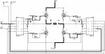
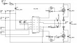
I need to control a 24V motor with an 18M2 high-power project board but using external FETs (SMP60N05) because of the power involved. I have got the motor running with PWM but need to be able to reverse it, hence the full bridge drive circuit. To avoid damaging either the motor or the FETs I would prefer if the 18M2 would check to see if speed is zero before reversing direction (and if not, ramp down to zero and wait 5secs to ensure the motor has stopped turning). I also need to have an emergency stop feature with a physical action required before it will reset (speed to zero then wait 5 seconds). Can anyone help with the additional software please ?
 

Attachments

SAborn

Senior Member
I dont see how you can build a H bridge with 4 x N channel mosfets as per your schematic.

Regardless of the circuit design problems you simply need to ensure ALL mosfets are OFF before switching to reverse or forward.

It wont matter if the motor is still turning in a direction when a direction change is demanded.

Your circuit has no diodes to shunt EMF, and that will likely be a bigger cause of mosfet failure than any other reason with changing direction of the motor.

As for emergency stop, simply buy a emergency stop switch that has a big red button, that when hit latches until manually released. (locking ring release)

This way your program would then look for a trigger on a input pin for emergency stop on every loop through the program, and if activated it simply shuts down all outputs till the emergenct stop is released.
 

MartinM57

Moderator
Big red button emergency stops should cut the entire power system rather than set a logic level on a cable connected to a pin that needs to be detected by hardware/software - for fairly obvious reasons, I would have thought.

IMHO.
 

Videostar

New Member
The power FETs have built in reverse diodes but it wouldn't be to much of a problem to add extra diodes if you think they ought to be there.
The problem with the "Big Red Button" is that the control side (project board, speed control, Forward/Reverse switch and emergency stop button) all have to fit into an existing handset. The FETs and power supply are at the end of a 2m cable.
 

nekomatic

Member
You're driving MOSFET gates from a PICAXE via... a relay? That's... baroque :)

Shouldn't you be using P-channel MOSFETs on the high side?

Do you want to check that *actual* motor speed is zero, or just check that the speed you have told the motor to do is zero - the former is going to need some circuitry, obviously.

Is the 'emergency stop' needed because the running motor could cause actual damage or injury? Because in that case it shouldn't go through a PICAXE, it should be an actual physical switch that isolates power to the motor.
 

Videostar

New Member
Martin, the motors, FETs and power supply are on a ride-on model train - the control (with the big red button) is travelling behind
 

Videostar

New Member
nekomatic - I'm trying to replace life expired equipment. The "old big red button" was a toggle switch that interrupted the power feed to the speed control pot. I can't find P-channel MOSFETs that will carry the current (up to 40A) at sensible money. I would be happy if the output from the PICAXE was zero - if it wasn't then the output needs to ramp down to zero and wait 5secs before ramping back up.
 

nekomatic

Member
But in your circuit, you're going to be dropping a few volts across the high side MOSFETs, otherwise they'll have no gate drive and won't turn on - that means you're losing power that should be going into the motor and your MOSFETs are going to get very hot.

I believe it should be possible to parallel MOSFETs for higher current handling but I haven't done this myself so perhaps someone else can advise - you may need a low value resistor on the source to ensure even distribution of the current for example.

If a toggle switch is acceptable as the 'emergency stop' then arrange your motor drive circuit so that a low on all control lines turns the motor off - which is normally the case with a P/N-channel H-bridge - and have the toggle disconnect power to the PICAXE circuit. The easiest way to enforce a five second delay before restart would then be to simply start your PICAXE program with a five second pause - would that be a problem in normal operation?
 

nekomatic

Member
There's an example H-bridge circuit here which (if you add pulldown resistors on the N-channel MOSFET gates) will default to 'all off' when the control inputs are all low or disconnected. It shows a 12 volt supply though so check the specs on the components you intend to use at 24V.
 

Dippy

Moderator
I think you may need to have another look at your circuit.

As said, with a pukka H-bridge you won't need relays to do reverse.
If you do use P-Chan then check the data sheets when using a 24V supply.
Study Vgs when doing designs, you'd need extra oomph gate volts when running N-types on the high-side.
For PWMing a motor (for speed control) you will need a proper MOSFET driver.

Have you done any calcs for powers and currents?
Or is the H-bridge block a COTS device and you are approximating it in your schematic.

For a ride-on device I would think a little harder regarding E-Stop.
If you can't do as Martin suggests then consider some other options.
A baby push-button to a micro is possibly not adequate where personal safety is involved.
I would NEVER use a toggle for an e-stop - the whole point is that you can activate it in panic mode and NOT accidentally knock it back on.
That's why, for proper stuff, they tend to be a darned great red thing built like a tank.
And anything that can get a bashing needs to be tough and not some cheap spindly blob :)


Can you let us know your electronics skill/experience level so people can provide suitable advice.
And can a technical cock-up potentially lead to injury in this application?
 

tmfkam

Senior Member
In drills and lathes with emergency stop actions a hefty dump of DC is fed into both armature and field coils at the same time. This causes both to become magnetically attracted to one another and locks the motor within something like 1/3rd rotation even from high speed.

If your motor doesn't have separate armature and field coils (which I presume it doesn't if you're using PWM) you might need to consider doing a full power reversal of the voltage through the motor for a second or two to achieve the same thing.

I built an H-Motor drive unit using IGBTs and this employed the IR2112 high side driver to ensure that the IGBTs (or in your case FETs) were driven into full conduction. I'm not certain if this would operate as low as 24V DC (I was using 380V DC - rectified mains) although I'm pretty certain that in the initial prototyping stages I had it running off 24V AC (safety first!).

The simplified diagram shows both halves of the bridge, demonstrating the flow of electricity when one half of the bridge is active. The left half circuit is shown in it's entirety in the other diagram, the right side being identical apart from the Drive_H - Drive_L inputs to the IR2112 being swapped.

Simple_H.jpg

Left_Pwr.jpg

As this unit dealt with potentially fatal live mains electricity, I fitted many safety features not shown in the simplified diagrams.
 
Top