Melexis to PICAXE

Profw

Member
Melexis to PICAXE

Gentlemen,

I was reviewing some posts that were made in 2013, they involved the Melexis MLX90614 IR thermometer. I obtained and copied the code to no avail. Has anyone actually made this sensor work with an 18M2+ ??? I set everything up including the pull up resistors, tested the sensor on an Arduino it was good,but just can’t get it to work with an 18M2+. Any ideas? Working code? Help? Thank you.

Chuck
 

hippy

Technical Support
Staff member
It would be worth showing the code you have, describing your hardware configuration and what results you got.
 

Profw

Member
The code is:
Code:
' MLX90614_08M2.Bas 
 ' (c)2011 by MR Burnette for all rights not reserved by PH Anderson
 ' Modified for M2 chips by Armp - Thanks Peter and Ray 1/12/13
 '
 ' 20M2 - Straight Drop In Replacement for 20X2,
 ' 08M2 - Connect 20X2 socket Pin 11 to Pin 17, Pin 13 to Pin 18,
 ' 196 Bytes
 '
 ' Modified by JlangholzJ and Armp for use in 18m2+
 ' Also modified for MLX90615
 ' 18M2+ - Stright drop in
 '
 #picaxe 18m2
 #No_Data

 SYMBOL Lo = B0 ' B1-B0 overmapped by W0 
 SYMBOL Hi = B1
 SYMBOL Temperature= W0

 SYMBOL PEC = B2
 SYMBOL RamLocation= B3 ' Could be a Constant in this example

 SYMBOL X = B4
 SYMBOL Tenths = B4 
 SYMBOL N = B5
 SYMBOL CRC8 = B6
 SYMBOL LOG_RATE = 1000 'Used as a pre-def for the logging rate (HZ)
 SYMBOL PAUSE_TIME = 1000/LOG_RATE

 SYMBOL SlaveAdr = B7

 SlaveAdr = $01 * 2 'shift left by a bit to allow read/write bit.

 sertxd("Beginning data:",CR,LF)

 Initialize:
 ' Return to this section on error condition on I2C bus CRC
 Hi2cSetup I2CMaster, SlaveAdr , I2CSlow, I2CByte

 Again: ' RAM location $07 is the object temperature in Kevin * 50 

 RamLocation = $27
 GoSub ReadRAM 
 If Temperature = 0 Then Error

 'Temperature = Temperature+2/5 'Use for Kelvin - integer divide by 5 with Rounding
 Temperature = Temperature - 12767 *3 /5 *3 /5 'to return Temp as xxx.xF - Armp 

 Tenths=Temperature//10 : Temperature=Temperature/10
 Sertxd ("Temp: ", #Temperature,".",#Tenths,CR,LF)
 Sertxd ("Addr: ", #SlaveAdr,CR,LF)


 Pause LOG_RATE ' Results in approx 1 reading per second 900
 ' MLX90614 requires 865ms to settle

 GoTo Again

 ReadRAM:
 Hi2cin RamLocation, (Lo, Hi, PEC) 
 CRC8 = $00
 X = SlaveAdr : GoSub CalcCRC8
 X = RamLocation : GoSub CalcCRC8
 X = SlaveAdr + 1 : GoSub CalcCRC8
 X = Lo : GoSub CalcCRC8
 X = Hi : GoSub CalcCRC8

 If CRC8 <> PEC Then
 Temperature = 0 ' Return Zero K if CRC Error
 Endif 

 Return

 CalcCRC8:
 X = X ^ CRC8
 For N = 0 to 7
 If X > 127 Then
 X = X * 2
 X = X ^ $07
 Else
 X = X * 2
 Endif
 Next
 CRC8 = X
 Return

 Error:
 Sertxd("ADDR ", #SlaveAdr, " Not valid", CR,LF)

 SlaveAdr = SlaveAdr + 1 'inc slave addr and re-init

 Goto Initialize 

 END
 
Last edited by a moderator:

Profw

Member
Code from forum PicAxe to Melexis

'
Code:
 MLX90614_08M2.Bas 
 ' (c)2011 by MR Burnette for all rights not reserved by PH Anderson
 ' Modified for M2 chips by Armp - Thanks Peter and Ray 1/12/13
 '
 ' 20M2 - Straight Drop In Replacement for 20X2,
 ' 08M2 - Connect 20X2 socket Pin 11 to Pin 17, Pin 13 to Pin 18,
 ' 196 Bytes
 '
 ' Modified by JlangholzJ and Armp for use in 18m2+
 ' Also modified for MLX90615
 ' 18M2+ - Stright drop in
 '
 #picaxe 18m2
 #No_Data

 SYMBOL Lo = B0 ' B1-B0 overmapped by W0 
 SYMBOL Hi = B1
 SYMBOL Temperature= W0

 SYMBOL PEC = B2
 SYMBOL RamLocation= B3 ' Could be a Constant in this example

 SYMBOL X = B4
 SYMBOL Tenths = B4 
 SYMBOL N = B5
 SYMBOL CRC8 = B6
 SYMBOL LOG_RATE = 1000 'Used as a pre-def for the logging rate (HZ)
 SYMBOL PAUSE_TIME = 1000/LOG_RATE

 SYMBOL SlaveAdr = B7

 SlaveAdr = $01 * 2 'shift left by a bit to allow read/write bit.

 sertxd("Beginning data:",CR,LF)

 Initialize:
 ' Return to this section on error condition on I2C bus CRC
 Hi2cSetup I2CMaster, SlaveAdr , I2CSlow, I2CByte

 Again: ' RAM location $07 is the object temperature in Kevin * 50 

 RamLocation = $27
 GoSub ReadRAM 
 If Temperature = 0 Then Error

 'Temperature = Temperature+2/5 'Use for Kelvin - integer divide by 5 with Rounding
 Temperature = Temperature - 12767 *3 /5 *3 /5 'to return Temp as xxx.xF - Armp 

 Tenths=Temperature//10 : Temperature=Temperature/10
 Sertxd ("Temp: ", #Temperature,".",#Tenths,CR,LF)
 Sertxd ("Addr: ", #SlaveAdr,CR,LF)


 Pause LOG_RATE ' Results in approx 1 reading per second 900
 ' MLX90614 requires 865ms to settle

 GoTo Again

 ReadRAM:
 Hi2cin RamLocation, (Lo, Hi, PEC) 
 CRC8 = $00
 X = SlaveAdr : GoSub CalcCRC8
 X = RamLocation : GoSub CalcCRC8
 X = SlaveAdr + 1 : GoSub CalcCRC8
 X = Lo : GoSub CalcCRC8
 X = Hi : GoSub CalcCRC8

 If CRC8 <> PEC Then
 Temperature = 0 ' Return Zero K if CRC Error
 Endif 

 Return

 CalcCRC8:
 X = X ^ CRC8
 For N = 0 to 7
 If X > 127 Then
 X = X * 2
 X = X ^ $07
 Else
 X = X * 2
 Endif
 Next
 CRC8 = X
 Return

 Error:
 Sertxd("ADDR ", #SlaveAdr, " Not valid", CR,LF)

 SlaveAdr = SlaveAdr + 1 'inc slave addr and re-init

 Goto Initialize 

 END
 
Last edited by a moderator:

PieM

Senior Member
Slave adress is $B4 for MLX90614 ($5A after shift left )

I use
Code:
hi2csetup i2cmaster, $B4, i2cslow, i2cbyte
and

Code:
        hi2cin $07, (b26,b27) 	'w13 Tobj. IR en 0.02 deg. Kelvin
	pause 10
	hi2cin $06, (b24,b25)	'w12 Tamb ambiante en 0.02 deg. Kelvin
	pause 10
 

Armp

Senior Member
Melexis to PICAXE

Gentlemen,

I was reviewing some posts that were made in 2013, they involved the Melexis MLX90614 IR thermometer. I obtained and copied the code to no avail.
Sorry I didn't see this before.

The code you copied was for a '615 diagnostic test. If you have a known good '614 the code in my post at #5 in thread http://www.picaxeforum.co.uk/showthread.php?23493-IR-temp-sensor
works with 08M2,14M2 and 20M2 - so probably should work for you...
 

Profw

Member
Thank you for you extra advice. After setting up the bread board, pull ups and code. I must admit at least I'm getting error... with one code version and CRC ERROR... with the other. I removed the if error code and the result was 326.8 no matter cold or hot. I tried to get in touch with Peter Anderson, spoke to his son, Peter has passed away we will miss him. Any other ideas???
 

Armp

Senior Member
I'm getting error... with one code version and CRC ERROR... with the other.
What code versions are you referring to? Stick with my original code, if you get CRC errors you have a bad sensor or a wiring error.
 

Profw

Member

Armp

Senior Member
Sensor is good. Wiring is good. I even tried the address suggestions from your post 5 of this subject.
And the code is good for other M2 chips. Is the 18M2 different?
BTW - if you have a 614 why even try the 615 code..

result was 326.8 no matter cold or hot
That indicates a CRC error.

If you want further help please provide a schematic, and clear photos. It would also help if you gave some indication of your technical background.
 
Last edited:

Profw

Member
To answer your questions let's start with my background. I started before college as an electronics technician, onto college then a field engineer, engineer, then inventor scientist, president of the Great Falls Science Robotics and onto well, that's enough. I'm a bit confused. I thought all this information your requesting was covered in the earlier posts. The code I'm using is code you modified from P.H. Anderson's and others. The MLX90614 is a four pin device simple to hook up. Pin 1 is SCL, pin 2 is SDA, pin 3 is +5 volts, pin 4 is ground. Both SCL and SDA are pulled high via 4.7 K resistors. That's the whole schematic. The 18 M2+ has designated pins 7 (SDA) and 10 (SCL)as the I2C connections. The hardware is easy, but the software which was previously written should work but does not. So, is this a software issue or is something awry with the 18M2+ ? It seems every time I try to get I2C devices (all) to work with the PICAXE I seem to run into trouble, I even went as far to order 20X2 chips and tried those as well with the same results. For some reason the MLX is not communicating with the AXE or visa versa. Is that enough information to help solve this problem. I know I deal with technical ineptness all the time, so I understand your concern. BTW, I have many of the MLX devices and have tested them all, they're all good. Any ideas as always are greatly appreciated.
 

Armp

Senior Member
Pin 1 is SCL, pin 2 is SDA, pin 3 is +5 volts, pin 4 is ground. Both SCL and SDA are pulled high via 4.7 K resistors. That's the whole schematic.
So you have no decoupling caps at all? How about the 10k/22k download circuit?

Seriously - you've tried a number of good 614s, multiple 18M2+ and 20X2, and Pete's, Ray's and my code - and nothing works for you. You've got a clean stable 5v supply with adequate decoupling? My money is on a wiring/layout problem.... 2 of 3 problems that I've helped solved with the 614/615 were because they were wired incorrectly. The pin diagram in the user guide (fig 2) is the bottom view. And the device needs a 0.1uF cap between Vdd and Vss pins.

If all this checks out - put a logic analyzer or scope on the scl/sda pins and check the traffic.

If that's good I'm out of ideas. Best I can offer is send me one and I'll test it for you, and return it.
 

Profw

Member
My layout is on an AXE 091 development board I use 3 AA batteries to run my experiments (4.5 volts DC). I guess I could use 4 NMHI batteries 1.25 X 4. These are good ideas. BTW, I've used these with other controllers with no problems noting that the pins on the 614 are viewed from the bottom. But maybe it's my axe 091?? More checking, I won't give up.
 

Profw

Member
Sure did. Taking your advice, I worked on the 614 18M2+ project again last night. I checked the sensor clock and data with my scope.... Hmmmm no signals. Checked pull ups good. Voltage, .1 cap, all good, chip, good went back to socket holding the 614, well what do you know, the power pin was bad and not making contact. I used the bread board this time to mount the 914. Checked with a scope, yes! Signals from the 914. Still the 18M2+ code was still not working. Set up the axe board for the good ol 20X2, it worked..... ambient temp displayed and target temp displayed!!! Yes finally. I guess if you work at something long enough you can solve anything with a little help from the forum. Now, what's the deal with the 18M2+??? back to the bread board. Do we have any code we know works with the 18M2+ and the 914? I see Jangholzj did some work with you. Did it work? Since that's the code I've been using for the 18M2+ part.
 

hippy

Technical Support
Staff member
BTW, I have many of the MLX devices and have tested them all, they're all good. Any ideas as always are greatly appreciated.
If the devices are working it most likely has to be either wiring or software, especially if others have had the same device working with the PICAXE.

A clear statement of exactly which device you are using, photos of your setup, details of the test code and result that gives, will probably help diagnose what the issue is.

Edited - crossposted with above - If it's working with the 20X2 it should work with an 18M2. Post your 20X2 and your 18M2 code.
 

Armp

Senior Member
well what do you know, the power pin was bad and not making contact.
Good! That comes under the category of a wiring problem in my book.
My money is on a wiring/layout problem
My money is intact!

I see Jangholzj did some work with you. Did it work? Since that's the code I've been using for the 18M2+ part.
One more time - that code was for a 615 and will NOT work for the 614.
The 20X2 code will NOT work with a M2 part.

My original code, from the link in post#7, without any mods, should work for your 18m2+.
It does not return the ambient temperature as I was not interested in that.

Edit: You MAY need to change the #picaxe 20M2 statement?
 

Profw

Member
Armp,
I went back to check most of the posts using the 18M2 with the 914. I tried a lot of the programs written, none of the 18 stuff worked. So, most likely I'm looking at the wrong posts. Could you please post a working 18M2 version that works, thank you. Here is a really interesting ordeal, while loading the code written by janholtzj I believe MLX90614_3.bas it's the code that asks for a slave address I may have given it an address that wiped the Axe code from the factory as it fried my 18M2+. It is no longer recognized by the editor. That's another question I have what version of Pic Axe editor do you use?
 

Goeytex

Senior Member
I believe MLX90614_3.bas it's the code that asks for a slave address I may have given it an address that wiped the Axe code from the factory as it fried my 18M2+.
Probably not "fried". Have you tried a HARD RESET yet ? See Manual 1 Page 50
 

Profw

Member
To avoid confusion here is the code I think your referring to: I found this from your link post #6 of IR temp Sensor I commented out your thoughts to help others in the future. Is this the right and ONLY code that works?
Also again, What editor version are you using?

'Quote Originally Posted by Armp View Post

'This code is for the MLX90614 and I've run it on 08M2, 20M2 and 20M2 so I think it should work for you.
'Used with mrburnettes permission.
'Many thanks to Pete Anderson and mrburnette!


Code:
' MLX90614_08M2.Bas	
' (c)2011 by MR Burnette for all rights not reserved by PH Anderson
' Modified for M2 chips by Armp - Thanks Peter and Ray 1/12/13
'
' 20M2 - Straight Drop In Replacement for 20X2,
' 08M2 - Connect 20X2 socket Pin 11 to Pin 17, Pin 13 to Pin 18,
' 196 Bytes
'
#picaxe 18m2
#No_Data
 
SYMBOL Lo 		= B0	' B1-B0 overmapped by W0 
SYMBOL Hi 		= B1
SYMBOL Temperature= W0

SYMBOL PEC 		= B2
SYMBOL RamLocation= B3  ' Could be a Constant in this example

SYMBOL X          = B4
SYMBOL Tenths	= B4	   
SYMBOL N          = B5
SYMBOL CRC8 	= B6
	
SYMBOL SlaveAdr = $5A * 2 'Hi2cSetup does not allow General Call 0 address.

sertxd("Beginning data:",CR,LF)

Initialize:
' Return to this section on error condition on I2C bus CRC
Hi2cSetup I2CMaster, SlaveAdr , I2CSlow, I2CByte

Again: ' RAM location $07 is the object temperature in Kevin * 50
  
    RamLocation = $07
    GoSub ReadRAM 
    If Temperature = 0 Then Error
        
   'Temperature = Temperature+2/5   	'Use for Kelvin - integer divide by 5 with Rounding
    Temperature = Temperature - 12767 *3 /5 *3 /5  'to return Temp as xxx.xF - Armp 
     
    Tenths=Temperature//10 : Temperature=Temperature/10
    Sertxd (#Temperature,".",#Tenths,CR,LF)
     
    Pause 900	' Results in approx 1 reading per second
                  ' MLX90614 requires 865ms to settle
    
 GoTo Again

ReadRAM:
    Hi2cin  RamLocation, (Lo, Hi, PEC)    
    CRC8 = $00
    X = SlaveAdr  	: GoSub CalcCRC8
    X = RamLocation	: GoSub CalcCRC8
    X = SlaveAdr + 1	: GoSub CalcCRC8
    X = Lo			: GoSub CalcCRC8
    X = Hi			: GoSub CalcCRC8
      
    If CRC8 <> PEC Then
       Temperature = 0		' Return Zero K if CRC Error
    Endif    
  
    Return

CalcCRC8:
   X = X ^ CRC8
   For N = 0 to 7
      If X > 127 Then
         X = X * 2
         X = X ^ $07
      Else
         X = X * 2
      Endif
   Next
   CRC8 = X
   Return

Error:
   	Sertxd("CRC Error...", CR,LF)
     	Goto Initialize   
   
END
Edit: Differences between '614 and '615

'I think you'll need to change
'SYMBOL SlaveAdr = $5A * 2 to
'SYMBOL SlaveAdr = $5B * 2

'And
'RamLocation = $07 to
'RamLocation = $27
 
Last edited by a moderator:

Armp

Senior Member
To avoid confusion here is the code I think your referring to: I found this from your link post #6 of IR temp Sensor I commented out your thoughts to help others in the future. Is this the right and ONLY code that works?
You did not copy from my post! Probably the same - don't know.

If you have a known good '614 the code in my post at #5 in thread http://www.picaxeforum.co.uk/showthread.php?23493-IR-temp-sensor
works with 08M2,14M2 and 20M2 - so probably should work for you...
And its customary to put code tags around long listings.

I used whatever Editor was available in late 2012.
 

Profw

Member
CONCLUSION for this post

I started this post October 21st of 2014 while experimenting with Melexis 90614 IR Temp sensors. I must thank everyone for all the comments and advice. Thank you for putting up with me with my lack of Forum etiquette. Some of you were very cross as though I did something terribly wrong. Others were very patient, but all were helpful.

Now onto the technical, the software was sketchy at least to muddle through all the programs on the forum, I wish people would conclude their findings and solutions. I have noticed posts will just end, and you say to yourself &#8220;did it work&#8221;? Did he finally solve the issue, but, maybe this is what forums are all about?

In my case here is what I found:
After frustration I can conclude, the reason the MLX device gave me so much trouble was a combination of software and hardware issues. Since it was recommended to use 4.7K Ohm resistors as pull ups on clock and data pins I did just that, only to find a 4.7K on the data pin is fine, but, If you don't want errors you need to place a 1K pull up on the clock pin. Now I can safely say for me anyway this solved all the 18M2+ problems I was having. BTW, I also needed to do the same for the 20X2 as well. That&#8217;s it, this project is concluded, a special thank you goes to Armp and others.

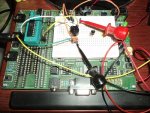
Please request photos of layout and scope waveforms as they are too large to download. There are 4 photos the breadboard, the laptop screen running the program, clock waveform on the scope, data waveform on scope.
 
Last edited:

Profw

Member
Yup, fried. Tried the Hard Reset. I 've lost a lot of 18M2+ like that in the past. They just stop being recognized.
 

Goeytex

Senior Member
If they are truly fried then you have serious supply or wiring problems or you are being careless and applying reverse voltage or overvoltage to the Picaxe. You cannot fry a Picaxe by writing the wrong address to another chip. Are you sure you are doing the hard reset correctly ?

Suggestion: Write a dummy program that is nothing more than Do : Loop. Then try reprogramming the "fried" chip using the hard reset. Some folks have a hard time with the hard reset because they apply the power too soon after starting the download. With no power applied to the Picaxe, start the download, then count to three and then apply power.
 

Profw

Member
I use three AA batteries to the 5 volt power jack on an Axe bread board. No over voltage, no reverse voltage. I lift one battery up out of the holder as a switch.
 

premelec

Senior Member
Profw - if you have any large capacitors on the power bus next to the AXE put a bleeder resistor on them or short them briefly with a 100ohm resistor to make sure you don't have any residual operating voltage during the hard reset - AND wait until the on screen message appears before applying power... it's pretty hard to get these chips to die yet you claim to have killed a bunch ! Maybe it's lightening?
 

westaust55

Moderator
Yup, fried. Tried the Hard Reset. I 've lost a lot of 18M2+ like that in the past. They just stop being recognized.
There is certainly something wrong if you are having failures with many PICAXE chips. SOme folks do have difficulty (not allowing enough time) for a "proper" hard reset.


From the PICAXE website FAQ page ( http://www.picaxe.com/FAQs/Fault-Finding/ )

What is a 'hard reset'?

A 'hard reset' is the means to force a PICAXE to respond to a download.
If the PICAXE is waiting for certain commands to complete (irin, kbin, serin, long pause commands and similar) the download request may not always be detected.

Initiating a 'hard reset' will cause the PICAXE to restart, let it see the download request and consequently download the new program.

For all PICAXE a 'hard reset' can be achieved by removing power and reapplying it soon after the download is initiated.

For the 28X2 and 40X2 (and earlier 28-pin and 40-pin devices, plus 18M and 18X) a 'hard reset' can also be achieved by taking the 'reset' pin low for a brief time.

Note that none of the PICAXE M2 devices have a 'reset' pin. When an 18M2 is used on a board designed for an earlier 18-pin PICAXE device any button marked as 'reset' may not actually reset the chip. In these cases removing power and reapplying it as described above will ensure a 'hard reset'.
Also from page 50 in PICAXE manual 1 ( http://www.picaxe.com/docs/picaxe_manual1.pdf )

To perform a hard reset using the power supply (all sizes):
1) Disconnect the power supply.
2) Wait until all power supply decoupling capacitors have discharged (can take up to 30 seconds or more depending on circuit design).
3) Click the PICAXE>Program menu to start a download.
4) Wait until the progress-bar appears on screen.
5) Reconnect the power supply
From steps 3 to 4 you will have around 3 seconds to react.
 

hippy

Technical Support
Staff member
As noted it is normally quite difficult to destroy a PICAXE chip and they often prove robust enough, for a time at least, to withstand the sort of events which could be expected destroy a chip, though that's by no means guaranteed. It is near impossible to erase or corrupt the firmware but it is possible to damage the physical silicon. As said, reverse voltage, over-voltage, sourcing or sinking too much current through an I/O pin, for example inadvertently making an input an output, or a wiring error can do that.

If you are seeing a lot of failures that could point to some systemic problem but it is more likely the chips are not responding to download because of the code previously downloaded not allowing it to respond to download initiations and a Hard Reset should recover those chips.
 

Armp

Senior Member
Since it was recommended to use 4.7K Ohm resistors as pull ups on clock and data pins I did just that, only to find a 4.7K on the data pin is fine, but, If you don't want errors you need to place a 1K pull up on the clock pin. Now I can safely say for me anyway this solved all the 18M2+ problems I was having. BTW, I also needed to do the same for the 20X2 as well.
IMO you have another wiring problem, or are systematically over stressing the SCL pins on all your the picaxes causing excess leakage.

Now onto the technical, the software was sketchy at least to muddle through all the programs on the forum
It could have been much easier IF you had heeded the advice given earlier:

#7 - If you have a known good '614 the code in my post at #5 in thread http://www.picaxeforum.co.uk/showthr...IR-temp-sensor
works with 08M2,14M2 and 20M2 - so probably should work for you...
#9 - Stick with my original code, if you get CRC errors you have a bad sensor or a wiring error.
We tried....
 

Profw

Member
I think I should clarify things a little. The chips that fried were not hooked up to anything but 4.7K ohm resistors (pin 7 and pin 10 respectfully), that's why your program which is the same only recopied on the forum from post 5 to 6 did not work for me. The SCL signal on pin 10 of the 18M2+ needed to be pulled higher. Now, with the same 18M2+ and the 1K resistor on pin 10, your code works great and the sensor always communicates. No 18M2+ fry problems so far.
 

Armp

Senior Member
I stand by my opinion above.

The I2C bus in 'slow' mode works fine with as much as 22K on a short net - so needing 1k indicates a LOT of leakage or a LOT of capacitance. My sample (of one) 614 leaks 12uA on the clock, so with 4.7k it reads about 70mV drop from Vdd.

BTW make sure Vdd is MORE than 4.5v - 3 tired AAs may not do it.

The chips that fried were not hooked up to anything but 4.7K ohm resistors
Maybe Hippy or Technical can comment on if it's possible to damage an 18M2 in such a configuration?

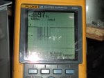
Can you resize the photos for upload? I'd like to see the SCL plot and the layout photo.
 
Last edited:

hippy

Technical Support
Staff member
The chips that fried were not hooked up to anything but 4.7K ohm resistors
Maybe Hippy or Technical can comment on if it's possible to damage an 18M2 in such a configuration?.
It doesn't seem likely to me. Even if the pins were set output low there wouldn't be enough current to cause damage to the I/O.

If connected to a module which was outputting high or low and the PICAXE output the opposite that could do it if there were no series current limiting resistors. Output high while an I2C line were pulling the line low might do it but such a situation would seem difficult to achieve for an actual I2C device, and would likely damage the I2C device as well..
 

Armp

Senior Member
Thanks.. A couple of questions

What is the vertical scale on the clock pulses? 2v/div?
What does 3.697 represent?
Whats the max those spikes go down to - looks well below 0v if thats the "-" marker?
 

Profw

Member
Yes, 2v/div. The total voltage peak supply with my tired AA batteries. Spikes are ringing below 0V. The design will use the 3.0 volt 614ESF part, but, since these are quite expensive I'm using the cheaper 5 volt version for testing purposes.
 
Top