interface help needed

Berny

Member
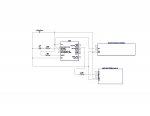
I am creating a security system that triggers a 18M2 to count down from 10 to 0 on a (https://www.sparkfun.com/search/results?term=com-11644) and activates an 08M2. There is a 315Mhz receiver (http://www.adafruit.com/product/1096) as part of the system such that if the keyfob is pressed the countdown will halt and not activate the 08M2. The schematic is below along with the test code. The problem is that when not connected to the 18M2, the 315Mhz receiver output shows 4.18 volts when activated which should be high enough to register a logical "1" but when connected to the 18M2 pin B.2 gets no higher than 0.35 volt, much to low. Any suggestions as to how to get the output to reach a logical "1" level would be appreciated along with any code enhancements.
Going out for the evening and will check the post tomorrow morning CST.

Thanks for any help.
Berny

DipTrace Schematic - 18M2Countdown.jpg

Code:
#picaxe 18m2
#no_data
#com 3
setfreq m8

symbol stp = c.2
symbol led = c.1
symbol stpflag = b0
symbol state = bit0
let b0 = 0
low b.3
symbol tx = c.0 		'this is connected to RX on display
symbol baud = T9600_8	'serial baud rate
low c.2
setint %00000100,%00000100,c

high tx
serout tx, baud, (0x7F)
serout tx, baud, (0x02)
serout tx, baud, (0x7A ,0x100) 'set brightness to 1/2
main:

	wait 1
goto main:
stpflag = 0

'serout tx, baud, (0x81) 'reset display to factory defaults
'pause 2000 'wait 1/2 second
'serout tx, baud, (0x76) 'clear display
'pause 20 'wait 10ms
'pause 2000 'wait 1 second
'serout tx, baud, (0x76) 'clear displ

interrupt:
pause 2000 'wait 1/2 second
serout tx, baud, (0x77,%00000010)	'set decimal point
serout tx, baud, ("10  ")		'set counter to 10 seconds
gosub chkflag:
pause 2000 'wait 1 second
serout tx, baud, (0x77,%00000010)	'set decimal point
serout tx, baud, (" 9  ")
gosub chkflag:
pause 2000
serout tx, baud, (0x77,%00000010)	'set decimal point
serout tx, baud, (" 8  ")
gosub chkflag:
pause 2000
serout tx, baud, (0x77,%00000010)	'set decimal point
serout tx, baud, (" 7  ")
gosub chkflag:
pause 2000
serout tx, baud, (0x77,%00000010)	'set decimal point
serout tx, baud, (" 6  ")
gosub chkflag:
pause 2000
serout tx, baud, (0x77,%00000010)	'set decimal point
serout tx, baud, (" 5  ")
gosub chkflag:
pause 2000
serout tx, baud, (0x77,%00000010)	'set decimal point
serout tx, baud, (" 4  ")
gosub chkflag:
pause 2000
serout tx, baud, (0x77,%00000010)	'set decimal point
serout tx, baud, (" 3  ")
gosub chkflag:
pause 2000
serout tx, baud, (0x77,%00000010)	'set decimal point
serout tx, baud, (" 2  ")
gosub chkflag:
pause 2000
serout tx, baud, (0x77,%00000010)	'set decimal point
serout tx, baud, (" 1  ")
gosub chkflag:
pause 2000
serout tx, baud, (0x77,%00000010)	'set decimal point
serout tx, baud, (" 0  ")
for b0 = 1 to 5				'trip BB servo
	high led
	pause 500
	low led
	pause 500
next b0
setint %00000100,%00000100,c
return

chkflag:
state = pinb.2
if pinb.3 <> state then
stpflag = 1
goto main
endif
setint %00000100,%00000100,c
return
 

Attachments

westaust55

Moderator
From the reciever data:
The M4 momentary type acts like a push button - when the A button is held down, the matching pin goes high. When the A button is released, the matching pin goes low. The pins only go high when a button is pressed.
This parts is correct:
&#8220; when not connected to the 18M2, the 315Mhz receiver output shows 4.18 volts when activated which should be high enough to register a logical "1" &#8220;​
but problem is:
&#8220;when connected to the 18M2 pin B.2 gets no higher than 0.35 volt, much to low.&#8221;​
This could be a poor connection for the connection from the RF receiver ground to the PICAXE ground so the signal is floating, or are you even measuring at the right PICAXE IO pin (see below)

For the SETINT command, from PICAXE manual 2:
This can be a combination of pins on the default input port (portC). X2 parts can
also be redirected to look at a different port if required.
Your SETINT command as:
setint %00000100,%00000100,c
being for an M2 part does not need the &#8220;C&#8221; parameter but is otherwise okay.
However the schematic has the RF receiver connected to pin pin 8 which is B.2.
If this is how it is actually wired then SETINT will not work. May explain if you are measuring at C.2 but have the signal wired to B.2
 

Goeytex

Senior Member
To add to the above. B.2 is made an output in the chkflag subroutine, so when taken low it will never read 4 volts regardless of the signal level from D2 on the RF module. The program is set to interrupt on C.2 high, but then C.2 is used as an output. This will never work properly.
 

westaust55

Moderator
B.2 is made an output in the chkflag subroutine.
chkflag:
state = pinb.2

This checks/logs the logic level at pinb.2 - not setting it

or am I missing something . . . .


but then C.2 is used as an output.
This is certainly the case

symbol stp = c.2
symbol led = c.1
:
:
symbol tx = c.0 'this is connected to RX on display
low c.2

pinC.2 is physical leg 1 on the 18M2 which in the DIPTRACE schematic is not connected to anything.
 

hippy

Technical Support
Staff member
The 'chkflag' routine also does a GOTO main which may prevent further interrupts occurring, but the pin not reading high problem most likely seems a wiring issue.
 

Berny

Member
additional info

c.2 is being triggered by another device and this part works. B.2 is supposed to be reading the "level" from the 315Mhz receiver. I corrected the typo in the code from:
state = b.2
if b.3 <> state then

to

if b.2 <> state then. Would this be correct then?
 

hippy

Technical Support
Staff member
if b.2 <> state then

To read the input signal on pin B.2 that would need to be -

if pinb.2 <> state then
 

Goeytex

Senior Member
chkflag:
state = pinb.2

This checks/logs the logic level at pinb.2 - not setting it

or am I missing something . . .
You missed something.

From the original code posted in the attached 18m2countdown.bas file .....

Code:
chkflag:
state = pinb.2
if pinb.2 <> state then
high b.2
stpflag = 1
low b.2
high led
pause 1000
low led
reset
endif
setint %00000100,%00000100,c
return
Either a low or high on b.2 will set the pin as an output.
 

hippy

Technical Support
Staff member
From the original code posted in the attached 18m2countdown.bas file .....
Well spotted. I had not realised the code pasted to the forum was not the same as the code contained in the attachment. I doubt many people would if they had not downloaded it.
 

westaust55

Moderator
Have you done some tests to verify that there is no wiring error holding the RF receiver signal line into the PICAXE low?

c.2 is being triggered by another device and this part works.
But the line
low c.2
makes it an output as already discussed so it will not be triggered by an external device and in fact may lead to circuit failure.

Suggest a full schematic and latest code together with clarification on the fault be posted so we are all working on the same page.

Maybe even consider using the PICAXE library for DIPTRACE developed by mycroft and myself with the latest chips rather than a schematic with IO labels as per the older 18M part to make the schematic easier to read.
See here:http://www.picaxeforum.co.uk/showthread.php?10576-DIPTRACE-PCB-Cad&p=78347#post78347
 

Berny

Member
Modified schematic using 18M2 picture. Attached modified code. Want to be able to stop the countdown with the keyfob activating the receiver output. Don't know how to clarify the idea.

View attachment DipTrace Schematic - 18M2Countdown.pdf

Code:
#picaxe 18m2
#no_data
#com 3
setfreq m8

symbol trg = c.2		'trigger from another 18M2 doing another task (works)
symbol led = c.1		'flashes when count gets to zero (works)
b0 = 0
symbol stpflag = b0
symbol state = bit0
symbol tx = c.0 		'this is connected to RX on display
symbol baud = T9600_8	'serial baud rate
low c.2
let dirsb = %11111011
setint %00000100,%00000100,c

high tx
serout tx, baud, (0x7F)
serout tx, baud, (0x02)
serout tx, baud, (0x7A ,0x100) 'set brightness to 1/2
main:
wait 1
stpflag = 0
goto main:

interrupt:
pause 2000 'wait 1 second
serout tx, baud, (0x77,%00000010)	'set decimal point
serout tx, baud, ("10  ")		'set counter to 10 seconds
gosub chkflag:
pause 2000 'wait 1 second
serout tx, baud, (0x77,%00000010)	'set decimal point
serout tx, baud, (" 9  ")
gosub chkflag:
pause 2000
serout tx, baud, (0x77,%00000010)	'set decimal point
serout tx, baud, (" 8  ")
gosub chkflag:
pause 2000
serout tx, baud, (0x77,%00000010)	'set decimal point
serout tx, baud, (" 7  ")
gosub chkflag:
pause 2000
serout tx, baud, (0x77,%00000010)	'set decimal point
serout tx, baud, (" 6  ")
gosub chkflag:
pause 2000
serout tx, baud, (0x77,%00000010)	'set decimal point
serout tx, baud, (" 5  ")
gosub chkflag:
pause 2000
serout tx, baud, (0x77,%00000010)	'set decimal point
serout tx, baud, (" 4  ")
gosub chkflag:
pause 2000
serout tx, baud, (0x77,%00000010)	'set decimal point
serout tx, baud, (" 3  ")
gosub chkflag:
pause 2000
serout tx, baud, (0x77,%00000010)	'set decimal point
serout tx, baud, (" 2  ")
gosub chkflag:
pause 2000
serout tx, baud, (0x77,%00000010)	'set decimal point
serout tx, baud, (" 1  ")
gosub chkflag:
pause 2000
serout tx, baud, (0x77,%00000010)	'set decimal point
serout tx, baud, (" 0  ")
for b0 = 1 to 5				'trip BB servo
	high led
	pause 500
	low led
	pause 500
next b0
setint %00000100,%00000100,c
return

chkflag:
state = pinb.2
if pinb.2 <> state then
stpflag = 1
setint %00000100,%00000100,c
goto main
endif
return
 

AllyCat

Senior Member
Hi Benny,

Code:
symbol stpflag = b0
symbol state = bit0
......
chkflag:
  state = pinb.2
    if pinb.2 <> state then
The THEN will be executed only if the level on pinb.2 happens to change in the very brief period between the first and second instructions of "chkflag". I think they should be exchanged (i.e. state is the "last state" which you then update if it has changed).

Also, bit1 is a bit within b0, is that what you intend?

But that's a much better schematic than the previous one. :)

Cheers, Alan.
 

Berny

Member
used code from post #7

Allycat,
Thanks for the compliment on the schematic. I took the code originally from a search I did, on this forum, for checking the status of a pin. Basically I read it as bit0 held either a 0 or a 1 which is what I thought I wanted. I have no problem changing the code to whatever it needs to be. I have checked the wiring and it seems to be per the schematic. The countdown is working, I just want to stop it before it gets to 0 and activates the next device.

Thanks to all for the help and I should be a bit embarrassed at this being such a problem but then I'm more dense sometimes more than others and I am currently in the "more dense" mode with this problem. I will keep plugging away. I had thought a separate power supply might be needed but haven't tried that yet. I may order another receiver, only $4.95 but since it works "by itself" I have not done that yet either.
 

AllyCat

Senior Member
H Benny,

Some of the potential "gotchas" here are that "bit1" is exactly the same as bit 1 in the "b0" variable. Also, the PE always converts "b.2" to a pure number (in this case it's 2). Thus, someting like IF b.2 = 1....... can NEVER be true. That's why the "pinb.2" format is necessary (which does read in the pin's logical signal value).

A way to check on "nasties" like this is to use SERTXD, either in the PE Simulator or from a "real" PICaxe to the Terminal emulator. So you can try out instructions such as: SERTXD(#c.1," ",#pinc.1,CR.LF) etc., to see what the "internal" values are.

Cheers, Alan.
 

Berny

Member
code modification - still not working

Changed the code as attached below. Also attached results of SERTXD command within code:

Code:
#picaxe 18m2
#no_data
#com 3
setfreq m8

symbol trg = c.2
symbol led = c.1
symbol stpflag = b0
symbol state = bit1
symbol tx = c.0 		'this is connected to RX on display
symbol baud = T9600_8	'serial baud rate
low c.2
let dirsb = %11111011
setint %00000100,%00000100,c

high tx
serout tx, baud, (0x7F)
serout tx, baud, (0x02)
serout tx, baud, (0x7A ,0x100) 'set brightness to 1/2
main:
wait 1
stpflag = 0
goto main:

interrupt:
pause 2000 'wait 1/2 second
serout tx, baud, (0x77,%00000010)	'set decimal point
serout tx, baud, ("10  ")		'set counter to 10 seconds
gosub chkflag:
pause 2000 'wait 1 second
serout tx, baud, (0x77,%00000010)	'set decimal point
serout tx, baud, (" 9  ")
gosub chkflag:
pause 2000
serout tx, baud, (0x77,%00000010)	'set decimal point
serout tx, baud, (" 8  ")
gosub chkflag:
pause 2000
serout tx, baud, (0x77,%00000010)	'set decimal point
serout tx, baud, (" 7  ")
gosub chkflag:
pause 2000
serout tx, baud, (0x77,%00000010)	'set decimal point
serout tx, baud, (" 6  ")
gosub chkflag:
pause 2000
serout tx, baud, (0x77,%00000010)	'set decimal point
serout tx, baud, (" 5  ")
gosub chkflag:
pause 2000
serout tx, baud, (0x77,%00000010)	'set decimal point
serout tx, baud, (" 4  ")
gosub chkflag:
pause 2000
serout tx, baud, (0x77,%00000010)	'set decimal point
serout tx, baud, (" 3  ")
gosub chkflag:
pause 2000
serout tx, baud, (0x77,%00000010)	'set decimal point
serout tx, baud, (" 2  ")
gosub chkflag:
pause 2000
serout tx, baud, (0x77,%00000010)	'set decimal point
serout tx, baud, (" 1  ")
gosub chkflag:
pause 2000
serout tx, baud, (0x77,%00000010)	'set decimal point
serout tx, baud, (" 0  ")
for b0 = 1 to 5				'trip BB servo
	high led
	pause 500
	low led
	pause 500
next b0
setint %00000100,%00000100,c
return

chkflag:
state = pinb.2
SERTXD(#b.2," ",#pinb.2,CR,LF)
if pinb.2 <> state then
stpflag = 1
setint %00000100,%00000100,c
goto main
endif
return
2 0 keyfob not pressed
2 0
2 0
2 1 keyfob pressed (count continues)
2 0
2 1
2 1
2 0
2 0
2 0
 

westaust55

Moderator
I am still confused - you are not taking into consideration all the comments made by folks trying to help you.
.
You say and the schematic indicates that pin C.2 is triggered by an external device.
But in the code you have
symbol baud = T9600_8 'serial baud rate
low c.2LOW C.2​
which makes pin C.2 into an output.

The SETINT command is then trying to monitor pin C.2.

From within the Interrupt: subroutine, you are using the GOSUB to the chkflag: routine.
However within the chkflag: routine if the IF&#8230;THEN test passes then you have the
goto main​
so each time this occurs you return to the Main menu without using two RETURN command (at the and of the chkflag: routine and at the end of the Interrupt: command. This will cause the stack for return addresses to overflow after a couple of these goto Main commands.
Further, without executing a RETURN, I understand that the SETINT command is not again restarted.
See the notes in the SETINT command section in PICAXE manual 2
2) When the interrupt occurs, the interrupt is permanently disabled. Therefore to re-enable the interrupt (if desired) a SETINT command must be used within the interrupt: sub-procedure itself. The interrupt will not be enabled until the &#8216;return&#8217; command is executed.
I recommend that you need to set a flag within the chkflag: routine that can be checked and used to skip/branch directly to the RETURN command in each sub-routine rather than a GOTO Main:

Note also that in a GOSUB command, you do not need the colon at the end of the subroutine name (only needed at the label at the start of the subroutine.
 

Goeytex

Senior Member
Hi Berny,

It seems you are having a bit of trouble with the use of variables, pin direction ( input or output), and program flow/structure. Attached is code that should do what you want but is completely restructured with what I think is acceptable formatting and commenting.

I am wrote this code so that you can see how the code might be better structured as well as to see the use of symbols, variables and flags. I swapped B.2 and C.2 around, so if you want to test, connect Pin C.2 to the receiver, and Pin B.2 to the other 18M2. I would use 10K pull down resistors on both of these lines.

This simulates fine in PE6. However, PE5 has a problem simulating the line: serout tx, baud, ($7A, $100) 'set brightness to 1/2. It seems the PE5 simulator doesn't like sending the $100 (DEC 256), so if you try to simulate in PE5, temporarily change the $100 to $FF. Here's the code:

Code:
[color=Green]'#picaxe 18m2[/color]
[color=Navy]#no_data
#com 3[/color]
[color=Blue]setfreq m8[/color]

[color=Green]' Connect Pin B.2 to the other 18M2 trigger outpuot
' Connect Pin C.2 to the Receiver Data line

' ***  May need to place 10K pulldown resistors on both C.2 and B.2 *** 


'constants [/color]
[color=Blue]symbol led [/color][color=DarkCyan]= [/color][color=Blue]c.1         [/color][color=Green]'Flashes when count gets to zero (works)[/color]
[color=Blue]symbol [/color][color=Purple]trg [/color][color=DarkCyan]= [/color][color=Purple]pinc.2      [/color][color=Green]'INPUT trigger from another 18M2 doing another task (works)[/color]
[color=Blue]symbol tx [/color][color=DarkCyan]= [/color][color=Blue]c.0          [/color][color=Green]'Pin C.0 is connected to RX on display[/color]
[color=Blue]symbol baud [/color][color=DarkCyan]= [/color][color=Blue]T9600_8    [/color][color=Green]'Serial baud rate 9600 non-inverted

'variables[/color]
[color=Blue]symbol [/color][color=Purple]stopflag [/color][color=DarkCyan]= [/color][color=Purple]b0[/color]
[color=Blue]symbol [/color][color=Purple]state    [/color][color=DarkCyan]= [/color][color=Purple]b1  [/color][color=Green]'Unused in this demo[/color]
[color=Blue]symbol [/color][color=Purple]counter  [/color][color=DarkCyan]= [/color][color=Purple]b2  [/color][color=Green]'General purpose counter[/color]
[color=Blue]symbol [/color][color=Purple]tmr      [/color][color=DarkCyan]= [/color][color=Purple]b3  [/color][color=Green]'used for delay timer[/color]

[color=Black]INIT: 
    [/color][color=Blue]let [/color][color=Purple]dirsb [/color][color=DarkCyan]= [/color][color=Navy]%11111011     [/color][color=Green]'// B.2 is input all other PortB pins are outputs   
    [/color][color=Blue]high tx                   [/color][color=Green]'// Set TX data line high
    [/color][color=Blue]serout tx[/color][color=Black], [/color][color=Blue]baud[/color][color=Black], [/color][color=Blue]([/color][color=Navy]$7F[/color][color=Blue])
    serout tx[/color][color=Black], [/color][color=Blue]baud[/color][color=Black], [/color][color=Blue]([/color][color=Navy]$02[/color][color=Blue])
    serout tx[/color][color=Black], [/color][color=Blue]baud[/color][color=Black], [/color][color=Blue]([/color][color=Navy]$7A[/color][color=Black], [/color][color=Navy]$100[/color][color=Blue]) [/color][color=Green]'set brightness to 1/2
    
    'Place a 10K resistor from Pinc.2 to ground.[/color]

[color=Black]MAIN:        
  [/color][color=Green]'// Wait for trigger from other 18M2
  [/color][color=Blue]DO     
     if [/color][color=Purple]PINB.2 [/color][color=DarkCyan]= [/color][color=Navy]1 [/color][color=Blue]then gosub [/color][color=Black]Countdown    
  
  [/color][color=Blue]LOOP        
  [/color]

[color=Black]COUNTDOWN:  
      [/color][color=Purple]stopflag [/color][color=DarkCyan]= [/color][color=Navy]0
      [/color][color=Blue]setint [/color][color=Navy]%00000100[/color][color=Black],[/color][color=Navy]%00000100  [/color][color=Green]'// enable interrupt on Pinc.2 high 
      [/color][color=Blue]pause [/color][color=Navy]2000 [/color][color=Green]'wait 1 second

      [/color][color=Blue]for [/color][color=Purple]counter [/color][color=DarkCyan]= [/color][color=Navy]10 [/color][color=Blue]to [/color][color=Navy]0 [/color][color=Blue]step [/color][color=DarkCyan]- [/color][color=Navy]1 
            [/color][color=Blue]serout tx[/color][color=Black], [/color][color=Blue]baud[/color][color=Black], [/color][color=Blue]([/color][color=Navy]0x77[/color][color=Black],[/color][color=Navy]%00000010[/color][color=Blue])   [/color][color=Green]'set decimal point
            
            [/color][color=Blue]if [/color][color=Purple]counter [/color][color=DarkCyan]< [/color][color=Navy]10 [/color][color=Blue]then  [/color][color=Green]'add the perceeding space
                  [/color][color=Blue]serout tx[/color][color=Black], [/color][color=Blue]baud[/color][color=Black],[/color][color=Blue]([/color][color=Red]" "[/color][color=Blue])
            endif 
            serout tx[/color][color=Black], [/color][color=Blue]baud[/color][color=Black], [/color][color=Blue]([/color][color=Black]#[/color][color=Purple]counter[/color][color=Black],[/color][color=Red]"  "[/color][color=Blue])          
       
            [/color][color=Green]'// 1 second delay while testing stopflag every 10 ms  
            [/color][color=Blue]for [/color][color=Purple]tmr [/color][color=DarkCyan]= [/color][color=Navy]1 [/color][color=Blue]to [/color][color=Navy]100
                  [/color][color=Blue]pause [/color][color=Navy]20
                  [/color][color=Blue]if [/color][color=Purple]stopflag [/color][color=DarkCyan]<> [/color][color=Navy]0 [/color][color=Blue]then [/color][color=Black]exit_countdown
            [/color][color=Blue]next
      next  
      
      setint off [/color][color=Green]'disable interrupt 
      [/color][color=Blue]for [/color][color=Purple]counter [/color][color=DarkCyan]= [/color][color=Navy]1 [/color][color=Blue]to [/color][color=Navy]5     [/color][color=Green]'trip BB servo
            [/color][color=Blue]high led
            pause [/color][color=Navy]500
            [/color][color=Blue]low led
            pause [/color][color=Navy]500
      [/color][color=Blue]next [/color][color=Purple]counter

      [/color][color=Black]exit_countdown:
      [/color][color=Purple]stopflag [/color][color=DarkCyan]= [/color][color=Navy]0  [/color][color=Green]'clear the flag  
      'maybe clear the display here
      'and display an abort message, etc[/color]
[color=Blue]return   [/color][color=Green]'to main  [/color]

[color=Blue]INTERRUPT:  [/color][color=Green]'//  Data from receiver (High on Pinc.2) 
    
      [/color][color=Purple]stopflag [/color][color=DarkCyan]= [/color][color=Navy]1     [/color][color=Green]'set the flag
      [/color][color=Blue]setint [/color][color=Navy]%00000000[/color][color=Black],[/color][color=Navy]%00000000    [/color][color=Green]'Disabled 
      [/color][color=Blue]return   [/color][color=Green]'to countdown with stopflag = 1[/color]
 
Last edited:

Berny

Member
works perfectly!

Goeytex,
The code works perfectly Thank you for the lesson. I will work to be more structured in the future. It is tough for me to get over being simple minded and not use the best practice. I will use this as an example.
 
Top