lately i have decided to get around to playing with some wireless modules i have had for a while, they are spi interface and as i only have M2 series picaxe to play with i have to use the bit banging method to try and get these working.
the modules have been used before by goeytex and with thorough write ups and info provided for register settings ect however that was with X2 chips and i have been trying to get a working bit banging test done to just read the status of the devices or the different registers to verify i am getting back data that should show me the default values of the different registers.
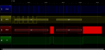
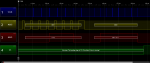
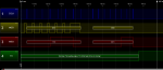
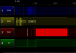
regardless of what i change in this code all i ever get back in B0 is %00001110, even if i try to read different registers nothing changes even with trying different setfreq speeds or looking at the miso line from module back to picaxe with a logic analyzer shows no data.
i have tried the different bit banged modes for shiftin relating to MSB first as the datasheet states but am still getting nowhere.
the datasheet is too large and wont let me attach it but links for it are provided in the original post by goeytex and others, its the BK2421 i.c
http://www.picaxeforum.co.uk/showthread.php?19036-Using-INHAOS-RF2400-2-4-gHz-RF-Modules
as this is my first time with bit banging and spi im sure their is something im missing even to just read the registers default values from power on but i dont know where to start
the modules have been used before by goeytex and with thorough write ups and info provided for register settings ect however that was with X2 chips and i have been trying to get a working bit banging test done to just read the status of the devices or the different registers to verify i am getting back data that should show me the default values of the different registers.
Code:
[color=Green]; *******************************************
; ***** INHAOS RF2400 Transmit / Receive ****
; *******************************************[/color]

[color=Black]DIRECTIVES:
  [/color][color=Navy]#picaxe [/color][color=Black]14m2
  [/color][color=Navy]#com 6
  #terminal 19200[/color]

[color=Black]SYMBOLS:[/color]
[color=Green];===========================================================================================
;============================ 14m2 pin assignments =======================================
;===========================================================================================
  [/color][color=Blue]symbol sclk [/color][color=DarkCyan]= [/color][color=Blue]b.1           [/color][color=Green]' clock (output pin)
  [/color][color=Blue]symbol mosi [/color][color=DarkCyan]= [/color][color=Blue]b.2             [/color][color=Green]' data (output pin for shiftout)
  [/color][color=Blue]symbol [/color][color=Purple]miso [/color][color=DarkCyan]= [/color][color=Purple]pinb.3          [/color][color=Green]' data (input pin for shiftin)
  [/color][color=Blue]symbol csn [/color][color=DarkCyan]= [/color][color=Blue]b.4              [/color][color=Green]' spi chip select (output, active low)
  [/color][color=Blue]symbol ce [/color][color=DarkCyan]= [/color][color=Blue]b.5               [/color][color=Green]' chip enable (output, 1=TX, 0=standby 1)


;===========================================================================================
;============================ bit bang spi symbols/variables ===============================
;===========================================================================================
  [/color][color=Blue]symbol [/color][color=Purple]counter [/color][color=DarkCyan]= [/color][color=Purple]b7           [/color][color=Green]' variable used during loop
  [/color][color=Blue]symbol [/color][color=Purple]mask [/color][color=DarkCyan]= [/color][color=Purple]b8              [/color][color=Green]' bit masking variable
  [/color][color=Blue]symbol [/color][color=Purple]var_in [/color][color=DarkCyan]= [/color][color=Purple]b9            [/color][color=Green]' data variable used durig shiftin
  [/color][color=Blue]symbol [/color][color=Purple]var_out [/color][color=DarkCyan]= [/color][color=Purple]b10          [/color][color=Green]' data variable used during shiftout

  [/color][color=Blue]symbol bits [/color][color=DarkCyan]= [/color][color=Navy]8               [/color][color=Green]' number of bits
  [/color][color=Blue]symbol MSBvalue [/color][color=DarkCyan]= [/color][color=Navy]128         [/color][color=Green]' MSBvalue (=128 for 8 bits, 512 for 10 bits, 2048 for 12 bits)


  [/color][color=Blue]symbol Config [/color][color=DarkCyan]= [/color][color=Navy]$00           [/color][color=Green]'Reg_address of Config Register
  [/color][color=Blue]symbol Status [/color][color=DarkCyan]= [/color][color=Navy]$07           [/color][color=Green]'Reg_address of Status Register
  [/color][color=Blue]symbol NOP [/color][color=DarkCyan]= [/color][color=Navy]255              [/color][color=Green]'no operation command, also used to get status/config register data


  [/color][color=Blue]symbol [/color][color=Purple]data1 [/color][color=DarkCyan]= [/color][color=Purple]b0


  [/color][color=Blue]let [/color][color=Purple]dirsb [/color][color=DarkCyan]= [/color][color=Navy]%00110111
  [/color][color=Blue]let [/color][color=Purple]dirsc [/color][color=DarkCyan]= [/color][color=Navy]%00000110

  [/color][color=Blue]high csn
  low ce

  pause [/color][color=Navy]3000

  [/color][color=Blue]setfreq m8[/color]

[color=Black]main:[/color]


[color=Blue]do
      pause [/color][color=Navy]1[/color]
[color=Blue]loop until [/color][color=Purple]pinc.3[/color][color=DarkCyan]=[/color][color=Navy]1[/color]

[color=Blue]pause [/color][color=Navy]4000[/color]


[color=Blue]let [/color][color=Purple]var_out [/color][color=DarkCyan]= [/color][color=Navy]%00000001    [/color][color=Green]'read bank 0, address 1 location,default value should be %00111111[/color]
[color=Blue]gosub [/color][color=Black]shiftout_MSBFirst[/color]


[color=Blue]gosub [/color][color=Black]shiftin_MSB_Pre[/color]
[color=Blue]let [/color][color=Purple]data1 [/color][color=DarkCyan]= [/color][color=Purple]var_in[/color]


[color=Blue]sertxd ([/color][color=Red]"Status  = "[/color][color=Black], #[/color][color=Purple]bit7[/color][color=Black],#[/color][color=Purple]bit6[/color][color=Black],#[/color][color=Purple]bit5[/color][color=Black],#[/color][color=Purple]bit4[/color][color=Black],#[/color][color=Purple]bit3[/color][color=Black],#[/color][color=Purple]bit2[/color][color=Black],#[/color][color=Purple]bit1[/color][color=Black],#[/color][color=Purple]bit0[/color][color=Black],[/color][color=Blue]CR[/color][color=Black],[/color][color=Blue]LF)


goto [/color][color=Black]main[/color]


[color=Green];===========================================================================================
;=========================== bit bang spi shiftout msb first ===============================
;===========================================================================================[/color]

[color=Black]shiftout_MSBFirst:

      [/color][color=Blue]low csn

      for [/color][color=Purple]counter [/color][color=DarkCyan]= [/color][color=Navy]1 [/color][color=Blue]to bits             [/color][color=Green]' number of bits
            [/color][color=Purple]mask [/color][color=DarkCyan]= [/color][color=Purple]var_out [/color][color=DarkCyan]& [/color][color=Blue]MSBValue     [/color][color=Green]' mask MSB
            [/color][color=Blue]high mosi                [/color][color=Green]' data high
            [/color][color=Blue]if [/color][color=Purple]mask [/color][color=DarkCyan]= [/color][color=Blue]MSBValue then [/color][color=Black]skipMSB
            [/color][color=Blue]low mosi                 [/color][color=Green]' data low[/color]
[color=Black]skipMSB:
            [/color][color=Blue]pulsout sclk[/color][color=Black],[/color][color=Navy]1          [/color][color=Green]' pulse clock
            [/color][color=Purple]var_out [/color][color=DarkCyan]= [/color][color=Purple]var_out [/color][color=DarkCyan]* [/color][color=Navy]2         [/color][color=Green]' shift variable left for MSB
      [/color][color=Blue]next [/color][color=Purple]counter

      [/color][color=Blue]high csn

      return[/color]

[color=Green];===========================================================================================
;=========================== bit bang spi shiftin msb pre clock ===============================
;===========================================================================================[/color]

[color=Black]shiftin_MSB_Pre:[/color]

[color=Blue]let [/color][color=Purple]var_in [/color][color=DarkCyan]= [/color][color=Navy]0

      [/color][color=Blue]low csn

      for [/color][color=Purple]counter [/color][color=DarkCyan]= [/color][color=Navy]1 [/color][color=Blue]to bits             [/color][color=Green]' number of bits
            [/color][color=Purple]var_in [/color][color=DarkCyan]= [/color][color=Purple]var_in [/color][color=DarkCyan]* [/color][color=Navy]2           [/color][color=Green]' shift left as MSB first
            [/color][color=Blue]if [/color][color=Purple]miso [/color][color=DarkCyan]= [/color][color=Navy]0 [/color][color=Blue]then [/color][color=Black]skipMSBPre
            [/color][color=Purple]var_in [/color][color=DarkCyan]= [/color][color=Purple]var_in [/color][color=DarkCyan]+ [/color][color=Navy]1           [/color][color=Green]' set LSB if serdata = 1[/color]
[color=Black]skipMSBPre:
            [/color][color=Blue]pulsout sclk[/color][color=Black],[/color][color=Navy]1          [/color][color=Green]' pulse clock to get next data bit
      [/color][color=Blue]next [/color][color=Purple]counter

      [/color][color=Blue]high csn

return[/color]i have tried the different bit banged modes for shiftin relating to MSB first as the datasheet states but am still getting nowhere.
the datasheet is too large and wont let me attach it but links for it are provided in the original post by goeytex and others, its the BK2421 i.c
http://www.picaxeforum.co.uk/showthread.php?19036-Using-INHAOS-RF2400-2-4-gHz-RF-Modules
as this is my first time with bit banging and spi im sure their is something im missing even to just read the registers default values from power on but i dont know where to start
Last edited: