Hi,
I want to build a picaxe thermostat to drive a heater for a wax pot. The existing 25 year old LCD display in the controller had died but the SSR which it drove is ok so can be re-used. Got this running in simulation switching on/off fine but ideally I would like to have a degree of variable hysteris (not sure of the word, brain dead!) so I could set it to stop at 60c and come on again when the temp drops say 5 degrees. Was going to use 2 pots for the setpoints, viewing the setpoints with an interupt routine on C2 and drive the SSR via an existing transistor from B0.
Been dabbling with this for ages on and off, looked at the code snippets but nothing really fits. Sorry its a PLF with all its limitations, but its the best I can do! Anyone solved a simlar problem?
Thanks Peter
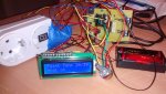
Attachments
-
51 KB Views: 25