HD44780 Display and Picaxe 08M2

JSDL

Senior Member
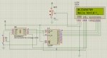
Hi all, I am trying to get an HD44780 parallel display to work with an 08M2 chip. I have successfully simulated the circuit using Picaxe VSM and it works perfect, however, when I built it it did not display anything at all. Is there something I am missing? Any help would be appreciated. Here is the code:

Code:
pause 100

'############################Define Sysmbols for 74HC595 and HD44780 pins

symbol shift595_CLOCK=c.0 	'Shift clock and Storage clock of 74HC595 are joined
symbol shift595_DATA=c.1
symbol LCD_LATCH=c.2		'Enable pin on HD44780 LCD module
symbol RS=c.4


symbol outbyte = b0
symbol counter = b1
symbol nibblecount = b2
symbol bitcount = b3

'###########################Send Inititialization commands

for counter = 0 to 6
	lookup counter ,($33, $32, $28, $10, $01, $06, $0F), outbyte
	low RS
	gosub WRITE_LCD
next counter

'###########################Send Data
for counter = 48 to 57
	outbyte = counter
	high RS
	gosub WRITE_LCD
	'pause 100
next counter

'###########################Send Inititialization commands
counter = 0
	lookup counter ,($C0), outbyte
	low RS
	gosub WRITE_LCD

'#############Send Data
for counter = 0 to 12
	lookup counter ,("Hello World!!"), outbyte
	high RS
	gosub WRITE_LCD
next counter

end


'###########################Write data/instructions to the LCD Subroutine
WRITE_LCD:

for nibblecount = 1 to 2
	for bitcount = 0 to 3
		if bit7 = 1 then
		high shift595_DATA
		else
		low shift595_DATA
		endif
	pulsout shift595_CLOCK, 1
	
	outbyte=outbyte * 2
next bitcount

pulsout shift595_CLOCK, 1
pulsout LCD_LATCH, 1

pause 4
next nibblecount
return
 

BeanieBots

Moderator
Probably a good idea to post your circuit as well.
Have you played with the contrast? Turn it up until the character boxes just begin to appear.
 
Last edited:

hippy

Technical Support
Staff member
You seem to be pulsing the 'shift595_CLOCK' five times for every command / data nibble sent.

That doesn't seem right to me for driving a parallel LCD in 4-bit mode and I wouldn't have expected it to work either in real life or under VSM simulation.
 

JSDL

Senior Member
the power source is a 5V DC wall adapter, tried playing with the contrast, now I can see boxes but no text.
 

hippy

Technical Support
Staff member
tried playing with the contrast, now I can see boxes but no text.
That's good in that it means the LCD is working but likely indicates the LCD is not being initialised - especially if first and third line are blocks on a four line display, lines two and four blank.
 

JSDL

Senior Member
I'm looking at the initialization sequence on P.40 of the Picaxe manual #3, and two things confuse me:

1) on line 5 of the init routine (let pins=48), why is the LCD set to 8 bit mode and then to 4 bit mode on line 10 (let pins =32)? Is this just how the LCD is initialized?

2) why is the enable pin pulsed 3 times after setting 8 bit operation, then twice after setting 4 bit operation. Does the LCD need to have the same command sent multiple times on initialization?

Any answers to these would be greatly appreciated. I'm really trying to learn how all this stuff works!!
 
Top