ERF connection to shield base
- Thread starter jinx
- Start date
I am not aware of any plans for a Shield Base which would support direct on-board connection of an ERF module.
For traditional (non-programming) wireless communications an ERF can be connected via a Shield or direct to the to-Shield headers.
For wireless programming an ERF can be connected to the H2 and H3 configuration links - single flying wires with 0.1" header sockets on the ends would be ideal for doing that.
It may also be possible to cut tracks from the PICAXE to the to-Shield header pins, link Serial In (RXD) and Serial Out (TXD) to those header pins and connect an ERF via a Shield using those connections.
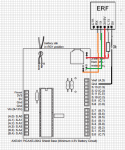
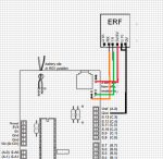
noticed that in the image " thats how it is in the manualDiagram looks correct except you seem to be powering the ERF from 3V3 with the Shield's 5V link set. Also CTS must be connected to 0V to enable it.
can I do away with the 10k resistor and jump the VTS to 0vCTS must be connected to 0V to enable it.
Last edited:
Which Manual ? I can investigate further.thats how it is in the manual
Yes.can I do away with the 10k resistor and jump the VTS to 0v
hi,
I just published a case for the erf on TGVhttp://www.thingiverse.com/thing:499057 its as basic as it comes
I just published a case for the erf on TGVhttp://www.thingiverse.com/thing:499057 its as basic as it comes
serout from the erf to the computer with the erf on the shield and a couple of jumpers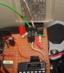 able to program the 14m2 aswell found a test piece of code from hippy in another thread
now to work out how to get the terminal window to send a value to the erf
able to program the 14m2 aswell found a test piece of code from hippy in another thread
now to work out how to get the terminal window to send a value to the erf
able to program the 14m2 aswell found a test piece of code from hippy in another thread
Code:
#picaxe 28X2
#no_data
#no_table
#terminal 9600
                                 ;

setfreq m8
low C.1 ; NB! ensure ERF RX is held low
 ; even when not used in this program
main:


Do
  Pause 2000
  SerOut c.7, N9600_8, ("Hello ", #w0, CR, LF )
  w0 = w0 + 1
Loopserin serout test the 28x2 receives a value of the key press and returns the value into the terminal
Code:
  ; ERF RX to PICAXE TX (C.1)
  ; ERF TX to PICAXE RX (C.7)
  ; ERF CTS to 0V

#picaxe 28X2
#no_data
#no_table
#terminal 9600
                                 ;

setfreq m8


main:


Do
  pause 10
  serin c.1,N9600_8,b0
   gosub sendback

   loop

   sendback:

  SerOut c.7, N9600_8, ("Hello ", #b0, CR, LF )

  return