Question about PCB design and ratings

Steve2381

Senior Member
Hi all
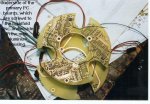
Currently trying to transfer my car lighting controller over from its current breadboard build, to a nice PCB.
Designing it on Express PCB, and will have a go at various methods of transferring it to a board (can't afford the actual PCBExpress price of £179!)

My question is that of power rating of the copper strips. I currently have 10x standard car 30A relays (the type with Lucas terminals on them), but plan to switch over and use something like these:

http://www.rapidonline.com/design-technology/omron-g8p-spno-30a-pcb-relay-518300

How do you know what width to make the PCB track to take a certain load? I am assuming basically... make them as wide as I can!

As a quick add on question.... the method of ironing photo paper onto a cleaned PCB board... does that work well on thin tracked detailed boards?
 

Steve2381

Senior Member
Ahhh.. thanks. I will find out the copper thickness and have a go.

Slightly off topic... I have a pile of old printers and scanners in my workshop. Do you reckon the stepper motors and drivetrains have enough guts to drive a small milling PCB machine? Complicated project I know.
I would have to Google how you convert the PCB data into milling head position, and how you track the heads position in the first place.... but hey... nothing like an ambitious project!
 

Hemi345

Senior Member
You might look into OSH Park for your design. $5/sq inch and you get 3 copies of your design. I've used them many times now and the turn around time from order placed to boards on my doorstep just keeps getting faster.
 

Steve2381

Senior Member
Oh - thanks Hemi. Just have to figure out how to convert the PCBExpress file into one they can use. Otherwise its do it again!
 

rq3

Senior Member
The copper on a PC board is generally measured in ounces per square foot, and "standard" material is 1 ounce copper. Typically another 1/4 ounce is plated onto the traces during the manufacturing process, and there is also a tin-lead or lead free "reflow" coat on top of that (thickness unspecified). The width of a trace for a particular current will depend on how much temperature rise the board can tolerate. For FR4 or G-10 board, a 30 amp trace would typically be 1030 mils (1.03 inches) wide for a 10 degree centigrade rise.

When getting into high currents, it is usual to make the board multi-layer, with one (or more) of the layers dedicated to the high current signals. This effectively makes the trace the size of the entire board, and also acts as a heat radiator surface.

For a price, ExpressPCB will convert your file to Gerbers, so that any fab house can make your boards. There are also converters on line (again, generally for a fee).

If you are making your own boards, the "art" of ironing resist onto the board can get you down to better than 10 mil traces and spaces IF you have good materials and good technique.
pcboards.jpg
 

Steve2381

Senior Member
Am I understanding that right then rq3? Over an inch wide for a 30A trace? My 30A relays are not actually taking 30A. Probably near 6A, but that is still a quite a wide trace.
Perhaps converting my 10x relays to a PCB board is not such a good idea. Even though I originally mounted the relays neatly in an enclosure, it still looks a mess with all the Lucas terminals looped together etc
I was just trying to make a more professional job of it.
 

Dippy

Moderator
Ec, yes. Obviously you are adding a conductor.

And, for multilayer boards don't forget track widths have to be fatter for internal layers for a given temp rise.

For cheaper 2 layer boards (and where convenient) you can do top&bottom layers with filled/solid vias to keep overall widths down.
The use of vias can really help in many board designs; RF too.
 

John West

Senior Member
I've been known to lay a heavy wire down along a high-current trace and liberally apply solder along its length in order to increase the current carrying capacity and reduce temperature rise and voltage drop. It's ugly, but it's mechanically and electrically reliable and works quite well.
 

Pongo

Senior Member
And a question for the grown-ups....

Can the tracks be "enhanced" with a thick layer of solder?
e
I'll confess to having done that but watch out that the track doesn't peel from the substrate. I think laying a wire on as per John West's post is probably superior. Having said all that I wouldn't recommend using standard PCB material for 30 amps.
 

Jeremy Harris

Senior Member
And a question for the grown-ups....

Can the tracks be "enhanced" with a thick layer of solder?

e
Yes, and and it's an awful lot more effective than I would have guessed. A chap on an EV forum tried an experiment on a brushless motor controller PCB by running a few tens of amps through some PCB tracks and measuring the temperature rise. He had been beefing up the tracks by soldering solid copper wire on to them (something I've done, and it works well but is fiddly to do) but decided to see how effective just flooding tracks with solder was. The results were unexpected, in that the tracks with solder only on didn't get any warmer than those with copper wires soldered on (and, like me, he was using thick copper wire to beef the tracks up)

I've found that it is easy to get a track 1/10th" wide and made from ordinary 1oz copper clad board to comfortably run at 20A when it's got solder pooled all along it, and it doesn't get noticeably warm (hard to tell, because I think most of the heat I was measuring may have been conducted down the power FET leads to the track). I've never seen more than 30 deg C on a track like this, even so, and that would seem to be OK.

I have some 2oz board that I used to make a high power (as in around 60A) controller, but it takes ages to etch compared to the thinner stuff, and the difference in current carrying capacity can easily be countered by just pooling solder on the high current tracks anyway.
 

Pongo

Senior Member
Yes, and and it's an awful lot more effective than I would have guessed. A chap on an EV forum tried an experiment on a brushless motor controller PCB by running a few tens of amps through some PCB tracks and measuring the temperature rise. He had been beefing up the tracks by soldering solid copper wire on to them (something I've done, and it works well but is fiddly to do) but decided to see how effective just flooding tracks with solder was. The results were unexpected, in that the tracks with solder only on didn't get any warmer than those with copper wires soldered on (and, like me, he was using thick copper wire to beef the tracks up).
Counterintuitive to say the least when the resistivity of both tin and lead is around 6-10 times higher than copper.
 

Jeremy Harris

Senior Member
Counterintuitive to say the least when the resistivity of both tin and lead is around 6-10 times higher than copper.
Indeed, so much so that I had to eat humble pie when I saw the results, as I was sure it wouldn't be as effective as it turned out to be! The chap who did the test videoed it to prove the point, as he was as surprised as I was (he also thought that the solder wouldn't work, which is why he did the test).

The reason this testing came about was because quite a few of us had been modifying Chinese made brushless motor controllers and in the process had routinely been sucking off the mountains of solder the manufacturer had applied to the high current tracks and replacing it with copper wire (in my case I used to put a strand of 2.5mm² solid wire stripped from T&E mains cable offcuts on to the tracks). This was a fair bit of work, and one person mentioned that they didn't bother and just left the solder on there without blowing any tracks (bearing in mind that peak current in some of these tracks would have been around 100A plus). To resolve the ensuing argument, a test was done which surprised a fair few of us, me included. I think the reason it works so well is just down the relatively large CSA, which can be greater than a track with a bit of 2.5mm copper wire soldered to it.
 

Dippy

Moderator
Well, we don't know:-
a) the diameter of the copper wire.
b) How thick the solder bead /pool is.
c) The method of measuring the temperature rise.
d) In Jeremy's para2; was the MOSFET taking heat from the track or supplying heat to it, or some of both - and does he mean 30oC or a rise in temp of 30oC over ambient?

All we do know is:-
a) Solder beading will be better than none.
b) Copper wire of same x-section will be better than solder.

Most people just do what they think works without calculation and their thumbometer to measure the temperature :)

Oh JH posted just after I clicked the thingy.

Now then, if you can put a perfect half-circle of solder on a 2.5mm track that will give you a lead/tin solder conductor with a CSA of 2.5mm sq.
Compare that with 2.5mm sq of copper ... and you say the solder is cooler?
Something wrong somewhere .. is it my calcs?

How was the temp measured, please don't say a IR Fluke thermal camera.
 

Jeremy Harris

Senior Member
The temp was measured with an IR thermometer, so won't be absolute, because of the low emissivity of shiny solder versus the reference emissivity these things are calibrated at (around 80% I think). It will be OK for comparison through, which is what Patrick did with his videoed test. In my case the temperature was very roughly measured at an indicated 30 deg C with an IR thermometer, as all I wanted to know was whether or not the tracks got warm when the controller was running at full power (a continuous 20A or so).

At a guess I would think that the actual track temperature may have been 5 or 10 deg warmer than my measurement (so perhaps as much as 20 deg above ambient), due to the emissivity error and averaging over the measured area (which had to have been a bit wider than the track, even with the gun held right against it). All I was interested in was whether it worked on that particular board or whether it would get too warm. It did work and the controller runs cool (and has run reliably in practice on one of my electric bikes for around 3 years now), so I no longer bother with the fiddly job of soldering copper wire along tracks (which is a very fiddly job when the tracks aren't straight and are relatively close to other tracks).

BTW, the tracks in question weren't a constant width, and squiggled around between MOSFET legs, so were around 0.2" in places (maybe wider) and down below 0.1" for very short lengths.
 

Pongo

Senior Member
Now then, if you can put a perfect half-circle of solder on a 2.5mm track that will give you a lead/tin solder conductor with a CSA of 2.5mm sq.
Compare that with 2.5mm sq of copper ... and you say the solder is cooler?
Something wrong somewhere .. is it my calcs?
That's where I come unstuck too. Suppose 100% tin, which is a better conductor than lead*, unless my math is also wrong the CSA for the same resistance as the 2.5 mm2 Cu would be something like 15 mm2

Oh, just saw JH latest post. If it works, it works, I guess :)

*mistype corrected.
 
Last edited:

John West

Senior Member
Another variable of possible interest with high current, high speed switching circuits, is Skin Effect, where trace surface area may matter more than a physically built-up trace. These days, with ever higher frequency everything, there are a lot of variables to be considered in good PCB design.
 

Steve2381

Senior Member
Wow.. this got involved really quickly! I am not pulling a full 30A through the board, but it needs to be safe and have enough capacity built in for extra loading.
Not sure I trust myself to design and build a suitable PCB now. Perhaps leave the high amperage stuff to cabled wiring and the control circuit on the PCB.
Never even considered heat etc
 

John West

Senior Member
In the final analysis, Steve, if you just make the high current traces as wide as you have room for, (use up all the extra bd space for the high current traces,) then check the heating of the traces under load, you'll likely be fine. The beauty of making your own bds is that you can afford to try them out and make better ones if they don't work like you want them to.
 

Pongo

Senior Member
Pongo: "Suppose 100% tin, which is a better conductor than copper"

What?
Oops, thanks for catching that, I have corrected it. My typing lagged my brain, that should have been "Suppose 100% tin, which is a better conductor than LEAD" - the other main component of solder.
 

Dippy

Moderator
But tin or lead is way down on conductivity compared to copper. So how can lead/tin or tin be cooler compared to copper of the same cross-sectional area? That was the point of my comments in post#16. And, will IR thermal measurements of a copper track be comparable to shiny solder? This all sounds very dubious.


Steve, I noticed in your 'Close Encounters' video that one poor oncoming vehicle briefly got a facefull of x-hundred watts of lighting before you dipped.
Is the complete lighting system linked to the dipped/main switch or a master switch?
Or is totally controlled by software (+switches of course)?
If your software/micro goes wrong can the lights get stuck on until you manually override?

I ask this as a work colleague fell off the road last winter when suddenly confronted by a lorry blazing with 16 additional spotlights plus 28 white LED clusters.
I see lorries and trucks loaded with lights all the time. I've had a full balst a couple of times and, esp when raining, had some close shaves.
 

Jeremy Harris

Senior Member
Dippy, your thinking is EXACTLY as mine was, until I saw the evidence with my own eyes.

I've come to the conclusion that it's probably to do with the rate of heat loss from the surface of the track that makes the difference. The rate of heat loss seems to be the dominant factor in rating the current carrying capability of conductors, AFAICS.

In this case, even though the solder has a far worse conductivity than copper, the increased cross section combined with the increased surface area seems to make it work. My controller that only has soldered tracks runs at a steady 20A or so flat out, with phase current peaks of around 70A through those tracks. In practice it doesn't even get noticeably warm in use, even after a hard spell of hill climbing. I've not done a "back-of-finger touch test", because these tracks have around 70V on them, but if they were getting hot then that heat would make its way out to the alloy case after a while, and it doesn't.

I'm certain that the IR thermometer will under-read when pointed at something so shiny, with an emissivity that's way off the calibration figure, but even so I doubt the reading was out by more than 50% or so.
 

Steve2381

Senior Member
Mmm... Its amazing how hard it is to find a quiet road to try your new lights on!

The lights are connected to full beam, but only when you have selected 'Off road' mode. I don't have them all connected normally - just asking for Police intervention.
I can select (in the software) how many lights are 'added' to full beam.

Each pair of led lights has its own relay. The system controls the coils and receives signals from full beam, ignition etc. Hopefully that means no situations where they all get stuck on.
However, every circuit is individually fused, so I can kill them should I need to. Pull the fuse to the Picaxe and you basically kill the system.

The battery level is also monitored. I can set a voltage level on the display that disables all the extra lighting if the battery gets too low.
 

Pongo

Senior Member
But tin or lead is way down on conductivity compared to copper. So how can lead/tin or tin be cooler compared to copper of the same cross-sectional area? That was the point of my comments in post#16. And, will IR thermal measurements of a copper track be comparable to shiny solder? This all sounds very dubious.
I agree. I think one of the foundations of this theory is dubious, 2.5 mm2 soldered onto a PCB track shouldn't be getting significantly hot at these currents. The wire by itself will be 0.00688 ohms per meter, let's suppose it's a 20 cm trace, so that's 0.001376 ohms, let's suppose a 30 amp average current, that would be 1.2 watts dissipated over the 20 cm length. Add the track and solder and it will be even less.

Is my calculation wrong?
 

tony_g

Senior Member
You might look into OSH Park for your design. $5/sq inch and you get 3 copies of your design. I've used them many times now and the turn around time from order placed to boards on my doorstep just keeps getting faster.
i second them, i use them all the time for my projects.

depending on what design software you use its just a matter of creating gerber files of your boards layers and then just changing the file format name for them from .gbr to the individual layer names for their system to recognise such as .gtl, .gko, .gts ect ect for the layers

it is alot easier than it sounds.


tony
 
Top