Integrating HTU21D temperature/humidity sensor using I2c using 18m2

rberkelm

New Member
Dear friends

I'm trying to implement a HTU21D temperature + humidity sensor on a Picaxe 18m2. This sensor by MEAS is a very tiny, but apparently very high spec'd (14-bit temperature and 12-bit humidity resolution) sensor at a very reasonable price (i.e. <$15 ea). The Datasheet for this sensor is beautifully detailed and laid out. My problem is that I just can't get it to work. Hopefully this is because I'm just not experienced enough at reading data sheets. Hence, would love your advice!

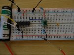
I have the sensor directly wired up to the SCLK and SDA lines of the 18m2 with a 4.7k pullup resistor on each line. I also have a 100 nF ceramic capacitor between the Vdd and GND lines as per the data sheet. My 18m2 is powered by the 5v IC on my Axe91u development board. My HTU21D sensor is powered by 2.5V via the Pot on the Axe91u board. My code is my interpretation of what is asked for in the data sheet (p10):

Code:
Main:
Pause 20
hi2csetup i2cmaster,0x80,i2cslow_8,i2cbyte  '%10000000 (hex 0x80) is device i2c bus address 
Pause 20
hi2cin 0xE5, (w0) '%11100101 to trigger humidity measurement, store in w0
pause 15
bintoascii w0,b2,b3,b4
debug
goto main
In debug I am just seeing "255" being returned in w0, meaning either the wrong i2c hardware configuration or wrong i2cslave data used (according to p72 of Picaxe Manual 2). I've tried swapping out sensors in case the first got a bit harshly treated with temperature (soldering) or voltage. The second sensor definitely had the "proper" treatment. Alas to no avail.

I think I've gone as far as I can with available resources and my skill level. I'd love some help to move me along on this?

Thanks
 

hippy

Technical Support
Staff member
The initialisation looks okay, correct I2C Device (0x80), so it could either be a voltage issue or a command issue assuming the hardware is otherwise okay.

If the module isn't pulling the SCL / SCK lines low enough signals might not be recognised by the PICAXE. It might be worth running the PICAXE from a bench supply and lowering that from 5V to see if it improves things.

0xE5 is a trigger-hold-reply command and that may be incompatible with PICAXE I2C and commands.

I am not familiar with the device and not sure how you would implement 0xF5 'no hold' I2C. One possibility would be to code software bit-banged I2C rather than use the inbuilt I2C commands.

You also have to read the two byte parts of w0 ( b1 then b0 ) rather than read a single w0.

Unfortunately I couldn't find any examples of using the HTU21D with a PICAXE on the forum or elsewhere but it might be worth a more detailed search with some time put into that.
 

BeanieBots

Moderator
Dear friends

My 18m2 is powered by the 5v IC on my Axe91u development board. My HTU21D sensor is powered by 2.5V via the Pot on the Axe91u board.
STOP before you kill your sensor.... if you haven't already!

Your 18M2 will be shoving 5v into the device which is 3v3 max.
The POT on my AXE91 is 100k (later ones are 10k) neither of which are remotely capable of suppling the current required for that sensor.

Your best bet is to run both the PICAXE and the sensor from a properly requlated 3v3 supply.
I've not looked at your code.
 

Hemi345

Senior Member
STOP before you kill your sensor.... if you haven't already!

Your 18M2 will be shoving 5v into the device which is 3v3 max.
Second this! You have the I2C lines pulled up to 5V which is much more than the absolute maximum ratings spec (see page 2 of the datasheet, "Digital I/O pins (DATA/SCK) to VDD").
 

Pongo

Senior Member
I'm trying to implement a HTU21D temperature + humidity sensor on a Picaxe 18m2. This sensor by MEAS is a very tiny, but apparently very high spec'd (14-bit temperature and 12-bit humidity resolution)
Sorry, but I'm conditioned like Pavlov's dog to comment that resolution does not equal accuracy.
 

rberkelm

New Member
Hey guys

Thanks for the replies. I'm happy to report success! As suggested, I breadboarded the components and am now running them off a 3.6v lithium battery, throttled to 3.0v via a diode. I'm also using a new sensor (luckily I bought a few!), although the first two might not have departed this world yet... (still hopeful!). Anyway the raw humidity numbers I'm getting are in the ball-park of those in the datasheet. Also when I breath on the sensor (Merlot flavoured :)), the numbers go up and come back down again after 15 sec or so. Very promising!

I also changed the code to store the raw values in b1 and b0 as w0 only gave a 3-digit result - thank you Hippy! Only thing is I don't understand why that should be the case - I thought word variables were made up of 2 bytes and in other comms protocols, saving large numbers into word variables seems to work? Is this a limitation of I2C?

Thanks heaps!
 

hippy

Technical Support
Staff member
I also changed the code to store the raw values in b1 and b0 as w0 only gave a 3-digit result - thank you Hippy! Only thing is I don't understand why that should be the case - I thought word variables were made up of 2 bytes and in other comms protocols, saving large numbers into word variables seems to work? Is this a limitation of I2C?
More a feature than a limitation.

I2C sends 8-bit byte chunks so having just 'w0' will read only the first byte into w0, the second byte is never read. Reading into b1 and b0 reads both bytes and automagically creates the full 16-bit value in w0 as b1:b0 are also the msb:lsb parts of w0.
 

rberkelm

New Member
In case it helps anyone, here is my final code, incl my version of dealing with the maths overruns. It seems to give good numbers but haven't tested calibration yet. I haven't had time to draw the circuit so hope the breadboard pic will suffice!DSC04245b.jpg

Note that the HTU21D sensor is ridiculously small (SMD, no 'legs') - about the size of a match head! However, soldering it onto a small SOT-23 PCB (eBay) was not as difficult as I thought. A minuscule amount of solder paste on each PCB pad, run the soldering iron along the side while pressing down on the sensor and done in a few seconds.

Abundant comments are included in the code for newbies like me who need them! Hope my interpretation is not too far off. I've deliberately NOT used labels for variables and constants... my brain just works better without them so far...

Code:
' Implementation of HTU21D temperature and humidity sensor with Picaxe 18m2. RH and Temp update ~every 2 sec.

Main:
Pause 20
hi2csetup i2cmaster,0x80,i2cslow_8,i2cbyte  '%10000000 (hex 0x80) is device i2c bus address 
hi2cin 0xE5, (b1,b0) '%11100101 to trigger humidity measurement, store in b1, b0 (automatically combined to w0)
hi2cin 0xE3, (b3,b2) '%11100011 to trigger temperature measurement, store in b3, b2 (automatically combined to w1)
pause 20

Calculate_RH: 
'Convert raw numbers to RH (%)
'Equation is: RH=-6+125xRawRH/2^16
w2=w0**125 'This is a large number which will overflow and return only the quotient (i.e. # overruns of 2^16)
'so no need to divide by 2^16!
w2=w2-6 'subtract constant from integer part of RH
w3=w0*125 'Remainder part of RH from overflow
w3=w3/655 'Decimal part of RH (as an approx. fraction of 65536)
sertxd ("RH = ",#w2,".",#w3,", ") 'Print RH to screen

Calculate_Temp: 
'Convert raw numbers to Temperature (deg C)
'Equation is: T=-46.85+175.72xRawTemp/2^16
w4=17572**w1 'Have already multiplied constant out by 100 to remove decimal fraction. Note: This returns # overruns 
'of 2^16, so no need to divide by 2^16!
b10=w4/100 ' Isolate integer part of quotient
b10=b10-46 'Subtract integer part of constant to get integer part of temperature
b11=w4//100 'Isolate decimal part of quotient

Decide_overruns:
if b11<85 then Adjust_integer_temp 
'else
b11=b11-85 'Subtract decimal part of constant from decimal part of temp
sertxd ("Temp = ",#b10,".",#b11,cr,lf) 'Print temp to screen
'debug
Pause 2000
goto main

Adjust_integer_temp:
b10=b10-1 '"Borrow" 1 from integer temp in order to subtract decimal part of constant
b11=b11+100 '"Add" 1 in front of decimal temp in order to to subtract decimal part of constant
b11=b11-85 'subtract decimal part of constant
sertxd ("Temp = ",#b10,".",#b11,cr,lf) 'Print temp to screen		
'debug
Pause 2000
goto main
 

marks

Senior Member
Hi rberkelm,
well done i do like your solution
some code you can try i think it should do the same
Code:
SYMBOL SensorRH     = W0       	   
SYMBOL Temperature  = W1  

SYMBOL Sign         = b7
SYMBOL D0           = b8
SYMBOL D1           = b9 
SYMBOL D2           = b10 
SYMBOL D3           = b11 
SYMBOL D4           = b12
' Implementation of HTU21D temperature and humidity sensor with Picaxe 18m2. RH and Temp update ~every 2 sec.

Main:
Pause 20
hi2csetup i2cmaster,0x80,i2cslow_8,i2cbyte  '%10000000 (hex 0x80) is device i2c bus address 
hi2cin 0xE5, (b1,b0) '%11100101 to trigger humidity measurement, store in b1, b0 (automatically combined to w0)
hi2cin 0xE3, (b3,b2) '%11100011 to trigger temperature measurement, store in b3, b2 (automatically combined to w1)
pause 20

Calculate_Temp:
       Temperature = Temperature **17572 -4685                       ' -40.00 to 125 °C                                 
       Sign = " "                                                    ' Display +   
     IF Temperature > 13000 THEN                       
       Sign = "-"                                                    ' Display - 
       Temperature = -Temperature                                    
     ENDIF 
          BinTOASCII Temperature,D4,D3,D2,D1,D0 
                  IF  D4 = "0" THEN : D4 = " "                       ' leading zero blanking 
                   IF D3 = "0" THEN : D3 = " " : ENDIF               ' leading zero blanking
                  ENDIF                                                                                                             
            sertxd (CR, LF, "  Temperature  ",Sign,D4,D3,D2,".",D1,D0,"°C")


Calculate_RH: 
		
		SensorRH = SensorRH **12500 -600                          ' -6.00 to 118 Rh%
		Sign = " "                                                ' Display +
	IF SensorRH > 13000 THEN                       
        Sign = "-"                                                    ' Display - 
        SensorRH = -SensorRH                                    
      ENDIF  
		 BinTOASCII SensorRH,D4,D3,D2,D1,D0 
                  IF  D4 = "0" THEN : D4 = " "                       ' leading zero blanking 
                   IF D3 = "0" THEN : D3 = " " : ENDIF               ' leading zero blanking  
	            ENDIF
            sertxd (CR, LF, "    SensorRH    ",Sign,D4,D3,D2,".",D1,D0,"%")
            		
Pause 2000
goto main
 

rberkelm

New Member
Marks: Wonderful mate, thanks for the time to tidy this up! It's like me painting a car with a brush and you doing it with a spray gun, clear coat etc...way more professional!

You've opened my eyes to a few things too. I hadn't thought about minus temps (not having ever had any here in tropical Townsville!). The zero blanking solution is cool too and your maths is way simpler!

Just one question: How did you get to a minus temp if "Temperature **17572 -4685 > 13000"? I would've thought temps would be -ve if the quotient of "Temperature **17572" got to < 4685? Similarly for RH, (also never contemplated a -ve RH...) but for the sake of it, I would've though RH would only go -ve if the quotient of "SensorRH **12500" falls below 600... which I think happens when SensorRH numbers get below 3146??

I'm ditching my code for yours... :)
 

rberkelm

New Member
Aw bugger.. just figured it out. If temp or RH go below zero, the numbers go large so anything beyond the normal range (12500 for temps and 11800 for RH) will be -ve numbers. Sorry, takes me a while...
 

marks

Senior Member
Hi rberkelm,
it proberly takes me longer than you to figure things out ...
i'm continuely surprised at all these new add on boards coming out
almost temped to buy this sensor to try seem about $11 on ebay
i guess we will have to wait for you evaluation of thumbs up lol.

Rich (BB code):
;  HTU21D   Digital Relative Humidity sensor with Temperature output
;           Recommended supplyvoltage is 3VDC (regulated).
#picaxe 18m2
SYMBOL SensorRH     = W0  SYMBOL RHmsb     = b1  SYMBOL RHlsb    = b0            
SYMBOL Temperature  = W1  SYMBOL TEMPmsb   = b3  SYMBOL TEMPLsb  = b2
SYMBOL Sign         = b4
SYMBOL D0           = b5
SYMBOL D1           = b6 
SYMBOL D2           = b7 
SYMBOL D3           = b8 
SYMBOL D4           = b9

Main:

Pause 20
hi2csetup i2cmaster,0x80,i2cslow_8,i2cbyte                            ' %10000000 (hex 0x80) is device i2c bus address 
hi2cin 0xE3, (TEMPmsb,TEMPLsb) : TEMPLsb = TEMPLsb AND 0xFC           ' Last bits of LSBdata ,
hi2cin 0xE5, (RHmsb  ,RHlsb  ) : RHlsb   = RHlsb   AND 0xFC           '  must beset to ‘0’ before calculating 
pause 20
            
Calculate_Temp:                                                      ; TempActual = TempSensor /65536 x175.72 -46.85
               Temperature = Temperature **17572 -4685                ' -40.00 to 125°C 14bit                               
               Sign = " "                                             ' Display +  
      IF Temperature > 13000 THEN                      
        Sign = "-"                                                    ' Display -
        Temperature = -Temperature                                   
      ENDIF
           BinTOASCII Temperature,D4,D3,D2,D1,D0
                   IF  D4 = "0" THEN : D4 = " "                       ' leading zero blanking
                    IF D3 = "0" THEN : D3 = " " : ENDIF               ' leading zero blanking
                   ENDIF                                                                                                            
           sertxd (CR, LF, "  Temperature  ",Sign,D4,D3,D2,".",D1,D0,"°C")          
           
RH_Compensated:         
               Temperature =Temperature /10                           ; RHcompensated = RHactual + (25 -TempActual) x -0.1
           IF Sign = "-" THEN : Temperature = -Temperature : ENDIF    ' improves RHaccuracy over 0.00 to 80.00°C
                                                                     
Calculate_RH:                                                        ; RHactual = RHsensor /65536 x125 -6
            SensorRH = SensorRH **12500 -600 + Temperature -250                         ' -6.00 to 118 Rh% 12bit
            Sign = " "                                                ' Display +
      IF SensorRH > 13000 THEN                      
        Sign = "-"                                                    ' Display -
        SensorRH = -SensorRH                                   
      ENDIF             
                 
          BinTOASCII SensorRH,D4,D3,D2,D1,D0
                  IF  D4 = "0" THEN : D4 = " "                       ' leading zero blanking
                   IF D3 = "0" THEN : D3 = " " : ENDIF               ' leading zero blanking 
                  ENDIF
            sertxd (CR, LF, "    RHcompensated    ",sign,D4,D3,D2,".",D1,D0,"%")  
                             
Pause 2000
goto main
 
Last edited:

rberkelm

New Member
Nice touches to improve accuracy! I saw the note in the data sheet about setting the Status bit (bit 1) to 0 but didn't know how, so thanks! Having said that, I'm not sure it makes much difference except to the 3rd decimal place. The temperature compensation could be important though. It's not on my April 2012 version of the data sheet, but have just seen that it is in the April 2014 revision. Thanks again for your input. In short, this is a sweat little sensor!
 
Top