Picaxe, PCA9555 and i2c

edmunds

Senior Member
Friends,

I am working on a project, where PICAXE-14M2 is driving a model car control solution. Since there are many parameters that should be set up once with DIP switches per street coming into the crossing, I have lead all those to PCA9995 I/O expanders. Also, there are too many outputs to reasonably control from PICAXE of any size directly, so I'm switching some of those through PCA9995s as well. Two important inputs of reed switch and IR sensor per incoming street are led directly to PICAXE-14M2 for easier programming and faster response.

I am now doing baby steps on i2c. The first thing I want is just to blink a LED through I/O expander. I don't have the PCA9555 here, but I got hold of PCF8574. They are not exactly the same, but seem close enough.

I think I understand the addressing bit of the whole thing. What I don't understand at all is read and write commands hi2cout and hi2cin. The data sheet of PCF8574 claims there should be START and STOP conditions sent. Also, there seems to be a requirement to "set" inputs and outputs on PCF8574 before sending anything. The third mystery is the ACK or acknowledgement.

How do one program all of this with hi2cout and hi2cin after that? Any experience with the I/O expander family in question? Datasheets and schematics of the project attached (sorry if the latter is a bit confusing after adjustments during routing the PCB).


View attachment ICCU_v_3.1_noPSU.pdf
View attachment PCF8574_PCF8574A.pdf

Thank you for your time,

Edmunds
 

Buzby

Senior Member
Hi Edmunds,

You don't need to worry about START,STOP, and ACK etc., the PICAXE firmware takes care of all those.

Just send data to an address on the I2C bus using HI2COUT, like this ...

HI2COUT [newslave],location,(variable,...)

The tricky part is knowing the address !.

I've not got time to go through your circuit in detail, but IC3 and IC6 seem to have address pins connected all to Vdd, which might put both chips at the same address. Is this wiring correct ?

Cheers,

Buzby
 

hippy

Technical Support
Staff member
There have been previous threads discussing interfacing with PCF8574 so a forum search on that will probably reveal further details and example code.

I don't believe the PCF8574 use a 'location' as Eeprom would so it's likely just a case of using -

HI2COUT ( data1, data2 )

and similar commands.
 

edmunds

Senior Member
Hi Edmunds,

You don't need to worry about START,STOP, and ACK etc., the PICAXE firmware takes care of all those.

Just send data to an address on the I2C bus using HI2COUT, like this ...

HI2COUT [newslave],location,(variable,...)

The tricky part is knowing the address !.

I've not got time to go through your circuit in detail, but IC3 and IC6 seem to have address pins connected all to Vdd, which might put both chips at the same address. Is this wiring correct ?

Cheers,

Buzby
Thank you, this worked. I am now happily blinking LEDs connected to two different chips.
IC3 and IC6 do have the same connections, but they also have different fixed portions of the address.

Edmunds
 

edmunds

Senior Member
There have been previous threads discussing interfacing with PCF8574 so a forum search on that will probably reveal further details and example code.

I don't believe the PCF8574 use a 'location' as Eeprom would so it's likely just a case of using -

HI2COUT ( data1, data2 )

and similar commands.
Hippy, thank you for your reply. I did try the search before and I tried it again now. Either I am doing something terribly wrong or the search engine is not very good. No results for me.

Edmunds
 

edmunds

Senior Member
Can you provide a list of inputs and outputs, and a rough outline of the workflow?
Will try. I did something similar on some other forum and a fellow contributor referred to it as a wall of text later on ;).

Inputs directly to PICAXE:
4x IR receivers 'waiting for SONY IR code 1-17 to determine what vehicle type is approaching the intersection

Outputs directly from PICAXE:
4x Servo 'go left - go straight - go right positions

Fixed DIP Switch I2C inputs:
4x layout off state route identification 'where cars are allowed to go when layout off signal is received - to get everybody home
4x no cars allowed emitting IR address 11 'battery low code
4x no cars allowed emitting IR address 12 'truck code
4x no cars allowed emitting IR address 13 'long vehicle code
4x no cars allowed emitting IR address 14 'bus code
4x no cars allowed emitting IR address 15 'emergency vehicle with emergency lights on code
4x no cars allowed emitting IR custom address 1
4x no cars allowed emitting IR custom addess 2
8421 inputs for 10-position custom address 2 selector (IR address 1-10)

Volatile I2C inputs:
4x reed switch to detect a car is approaching 'possibly duplicating the IR receiver in case all cars have PICAXE IR transmitters

I2C outputs:
4x STOP output
4x Blinker left output
4x Blinker right output
4x TrafficLight RED
4x TrafficLight YELLOW
4x TrafficLight GREEN
4x TrafficLight AUX

Ultimately, this should be enough control and processing power to run the traffic for the intersection. I have started writing the code in a way that running 4 traffic lights and storing the state stop/go for each approaching lane would be one task. In parallel, the code should be waiting for an approaching vehicle and on detection, should send it to the left, straight or to the left based on some more or less random procedure, BUT taking into account all the restrictions depending on the detected vehicle category and the positions of DIP switches.

Further complication would be yellow-only-mode, when cars would have to avoid collisions without the convenient guidance of traffic lights.

Hope this helps.

Edmunds
 

edmunds

Senior Member

lbenson

Senior Member
"Wall of text" or not, something like this is necessary to understand the scope of your very interesting project, and to be able to give assistance when asked without offering suggestions which would complicate actions in other parts of the system.

I'm still not sure that parallel processing (except with extra picaxe chips) would be needed or necessarily helpful. If you can process 16,000+ lines of code per second, you can probably do everything needed a good many times a second in one big loop. I am assuming that the size of the vehicles isn't such that a collision would harm persons or property (in which case parallel processing for some sorts of tasks might make it even harder to be confident of avoiding harmful interactions).
 

lbenson

Senior Member
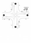
Next question--could you provide a drawing of the street net and signals?

Are these vehicles on tracks? If so, what kind of track? Do the servos provide switching (3-way) similar to (model) railroad track switches?
 

edmunds

Senior Member
"Wall of text" or not, something like this is necessary to understand the scope of your very interesting project, and to be able to give assistance when asked without offering suggestions which would complicate actions in other parts of the system.

I'm still not sure that parallel processing (except with extra picaxe chips) would be needed or necessarily helpful. If you can process 16,000+ lines of code per second, you can probably do everything needed a good many times a second in one big loop. I am assuming that the size of the vehicles isn't such that a collision would harm persons or property (in which case parallel processing for some sorts of tasks might make it even harder to be confident of avoiding harmful interactions).
Thank you for your reply. I do not insist on many processors and not on paralell processing either. If I manageto find another way. 16.000+ lines per second should be more than enough for everything, I agree. No harm on colision :). About 4cm for the smallest passenger cars and about 15cm for the longest trucks.

Edmunds
 

edmunds

Senior Member
Next question--could you provide a drawing of the street net and signals?

Are these vehicles on tracks? If so, what kind of track? Do the servos provide switching (3-way) similar to (model) railroad track switches?
Here you are. Not really on tracks, but they always do follow the same route. There is a wire in the street. And every car has a steering mechanism with a little arm extended in front with a small magnet that is folowing the wire in the street. The cars are self propelled, with LiPo batteries and packed with lots of tiny electronics. You do not buy them, you bild every single car with your bare hands :). You can search Dc-Car on youtube to see some examples. The function of the servos is extremely similar to model railroad track switches.

Thank you for your time.

Edmunds
 

Attachments

lbenson

Senior Member
I had an idle afternoon on a rainy day, so I set up how I would approach the structure of this project (with, admittedly, a limited understanding of it all).

With many I/Os, the PICAXE 40X2 seems like the chip to use, along with 4 MCP23017s for additional I/O. In addition, the 4 IRIN commands are blocking, so it is necessary to offload them to 08M2s.

This is how I see the I/O allocation on the 40X2:
Code:
2x23017 provide 4 ports of input dip switches for the 8 "route identification" conditions for 4 routes (2 i2c pins)

2x23017 provide 4 ports of 7 traffic light condition

4 08m2s provide IR receivers, each requires 2 i/o pins: b.0-b.3, d.4-d.7

4 servo pins: B.4-B.7

4 reed switch pins: D.0-D.3

2x 4-pin DIP switch custom address selector

Potential for hserin,hserout serial control: C.6, C.7 

unused: A.5, A.6, A.7
Code:
40X2 pinout diagram

                 *Reset  1 |             | 40 B7 Servo3
 DIP addr selector0a A0  2 | A0          | 39 B6 Servo2
        "         0b A1  3 | A1      A13 | 38 B5 Servo1 
        "         0c A2  4 | A2      A11 | 37 B4 Servo0
        "         0d A3  5 | A3       A9 | 36 B3 IR3 RTS&input
                  SERIN  6 |    40X2  A8 | 35 B2 IR2 RTS&input
              SEROUT A4  7 |    I/O  A10 | 34 B1 IR1 RTS&input
                     A5  8 | A5          | 33 B0 IR0 RTS&input
                     A6  9 | A6          | 32 +V
                     A7 10 | A7          | 31 0V
                     +V 11 |         A27 | 30 D7 IR3 CTS
                     0V 12 |         A26 | 29 D6 IR1 CTS
              Resonator 13 |         A25 | 28 D5 IR1 CTS
              Resonator 14 |         A24 | 27 D4 IR0 CTS
 DIP addr selector1a C0 15 |        HsIn | 26 C7 !tcpin
        "         1b C1 16 |         A18 | 25 C6 !tcpout
        "         1c C2 17 | A14     A17 | 24 C5 DIP addr selector1d
                 slc C3 18 | A4      A16 | 23 C4 sda
        reed switch0 D0 19 | A20     A23 | 22 D3 reed switch3
        reed switch1 D1 20 | A21     A22 | 21 D2 reed switch2
When an 08M2 gets an IR code, it raises a pin as a "Request To Send" (RTS) flag. When the 40X2 is ready, it raises a "Clear To Send" (CTS) pin and immediately goes into serin on the same line as the RTS to read the IR code (you could add a timeout to the serin to avoid locking up).

The main loop on the 40X2 sets up timer1 as a seconds timer. When the "toflag" (time-out) is high, indicating a new second, the program does its processing. The only code which is performed more than once a second is checking for a reed switch closing, since it looks like it might be closed and re-opened in less than a second. It's possible that the timing could require better than one-second response; if so, the code could be moved out of the seconds- timeout loop.

Each second, the program 1) checks for new IR detection; 2) reads the DIP address selectors; 3) reads the input switches from the mcp23017 i/o expanders; performs processing as needed; 4) sets servos; and 5) sets traffic light conditions and blinkers.

This code compiles, but is completely untested. It is only a structure, since I don't know what you want to do based on the sensors. I left many "fill in the blank" comments.

Code:
'40ModelCar monitors and controls model car setup
#picaxe 40x2

#terminal 19200 'turn on terminal after program load

symbol cRTSinBaud=n19200_16
symbol cI2CSpeed=i2cfast_16
  
; MCP23017 register address constants (from westaust55 tutorial)
SYMBOL mcp23017_0 = %01000000 ; $0100 A2, A1, A0, R/W all connected to 0V
SYMBOL mcp23017_1 = %01000010 ; $0100 A2, A1, A0, R/W all connected to 0V
SYMBOL mcp23017_2 = %01000100 ; $0100 A2, A1, A0, R/W all connected to 0V
SYMBOL mcp23017_3 = %01000110 ; $0100 A2, A1, A0, R/W all connected to 0V
SYMBOL IODIRA = $00 ; Port A IO Direction register DEFAULT = I/P
SYMBOL IODIRB = $01 ; Port B IO Direction register DEFAULT = I/P
SYMBOL GPIOA = $12 ; Port A General purpose register
SYMBOL GPIOB = $13 ; Port B General Purpose register

symbol pIR_RTS0 = B.0 ' IR detector 0 has new ir input
symbol pIR_RTS0pin = pinB.0 ' IR detector 0 has new ir input
symbol pIR_RTS1 = B.1 ' IR detector 0 has new ir input
symbol pIR_RTS1pin = pinB.1 ' IR detector 0 has new ir input
symbol pIR_RTS2 = B.2 ' IR detector 0 has new ir input
symbol pIR_RTS2pin = pinB.2 ' IR detector 0 has new ir input
symbol pIR_RTS3 = B.3 ' IR detector 0 has new ir input
symbol pIR_RTS3pin = pinB.3 ' IR detector 0 has new ir input
symbol pServo0 = B.4
symbol pServo1 = B.5
symbol pServo2 = B.6
symbol pServo3 = B.7

symbol pIR_CTS0 = D.4
symbol pIR_CTS1 = D.5
symbol pIR_CTS2 = D.6
symbol pIR_CTS3 = D.7

' b0-b3 reserved for bit variable
symbol routeIDFlags=b0 ' bit0-bit7
symbol bOffState=bit0
symbol bBatteryLow=bit1
symbol bTruck=bit2
symbol bLongVehicle=bit3
symbol bBus=bit4
symbol bEmergency=bit5
symbol bCustom1=bit6
symbol bCustom2=bit7

symbol servo0Pos=b4
symbol servo1Pos=b5
symbol servo2Pos=b6
symbol servo3Pos=b7
symbol oldServo0Pos=b8
symbol oldServo1Pos=b9
symbol oldServo2Pos=b10
symbol oldServo3Pos=b11
symbol IR0code=b12
symbol IR1code=b13
symbol IR2code=b14
symbol IR3code=b15
symbol address0=b16
symbol address1=b17

symbol wSecondsCount=w26 ' b52,3
symbol wScratch=w27 ' b54,5

SETFREQ M16
  pause 8000

  ' set up mcp23017 i/o expanders
  HI2CSETUP i2cmaster, mcp23017_0, cI2CSpeed, i2cbyte
  HI2COUT IODIRA, ($FF) ;set all port A pins as inputs (1)
  HI2COUT IODIRB, ($FF) ;set all port B pins as inputs (1)
  HI2CSETUP i2cmaster, mcp23017_1, cI2CSpeed, i2cbyte
  HI2COUT IODIRA, ($FF) ;set all port A pins as inputs (1)
  HI2COUT IODIRB, ($FF) ;set all port B pins as inputs (1)
  HI2CSETUP i2cmaster, mcp23017_2, cI2CSpeed, i2cbyte
  HI2COUT IODIRA, ($00) ;set all port A pins as outputs (0)
  HI2COUT IODIRB, ($00) ;set all port B pins as outputs (0)
  HI2CSETUP i2cmaster, mcp23017_3, cI2CSpeed, i2cbyte
  HI2COUT IODIRA, ($00) ;set all port A pins as outputs (0)
  HI2COUT IODIRB, ($00) ;set all port B pins as outputs (0)

  settimer t1s_16
  IR0code = 99 ' initialize to invalid code
  IR1code = 99
  IR2code = 99
  IR3code = 99

main:
  do
    if toflag = 1 then ' next second
      wScratch = t1s_16 + timer
      timer = wScratch  ' new setting for seconds timer
      toflag = 0
      inc wSecondsCount ' rolls over after about 18 hours, 12 minutes
      ' now decrement any seconds timers & perform required actions
      
      ' check for new IR detection
      if pIR_RTS0pin = 1 then ' new IR code ready
        high pIR_CTS0
        serin pIR_RTS0,cRTSinBaud,IR0code ' (add timeout if needed)
        low pIR_CTS0
        ' do what is needed for new ir code
      endif
      '(Same for other 3 ir code readers)
      
      ' read the DIP address selectors
      address0 = pinsA & %00001111 ' least significant nibble of portA
      b3 = pinsC & %00000111  ' least significant 3 bits of portC
      if pinC.5 = 1 then : bit27 = 1 : endif ' set 4th address bit
      address1 = b3
      ' now do something based on the address selectors
      ' ...

      ' read the input switches from the mcp23017 i/o expanders
      HI2CSETUP i2cmaster, mcp23017_0, cI2CSpeed, i2cbyte
      HI2CIN GPIOA,(routeIDFlags) ' read the route ID switches
      ' process route0 switches
      ' ...
      HI2CIN GPIOB,(routeIDFlags) ' read the route ID switches
      ' process route1 switches
      ' ...
      HI2CSETUP i2cmaster, mcp23017_1, cI2CSpeed, i2cbyte
      HI2CIN GPIOA,(routeIDFlags) ' read the route ID switches
      ' process route2 switches
      ' ...
      HI2CIN GPIOB,(routeIDFlags) ' read the route ID switches
      ' process route3 switches
      ' ...

      ' set OUTPUTs
      ' set servos as needed
      if servo0Pos <> oldServo0Pos then
        SERVOPOS pServo0,servo0Pos
        oldServo0Pos = servo0Pos
      endif
      if servo1Pos <> oldServo1Pos then
        SERVOPOS pServo1,servo1Pos
        oldServo1Pos = servo1Pos
      endif
      if servo2Pos <> oldServo2Pos then
        SERVOPOS pServo2,servo2Pos
        oldServo2Pos = servo2Pos
      endif
      if servo3Pos <> oldServo3Pos then
        SERVOPOS pServo3,servo3Pos
        oldServo3Pos = servo3Pos
      endif

      ' set traffic light conditions and blinkers
      ' ...
      
    endif ' end of "new second" code

    ' read reed switches
    if pinD.0 = 1 then ' do something or set a flag
    endif
    if pinD.1 = 1 then ' do something or set a flag
    endif
    if pinD.2 = 1 then ' do something or set a flag
    endif
    if pinD.3 = 1 then ' do something or set a flag
    endif

    
  loop
Regarding symbols, I put a "p" before a symbol for a pin, a "w" before a symbol for a word, and a "b" before a symbol for a bit. For byte symbols, I use not prefix character.
 
Last edited:

edmunds

Senior Member
Thank you. Unbelievable. I was never expecting "that much" help. Highly appreciated. Will try to dig through and figure out how you solved it and get back with some questions.

The video is of one of the top modellers for this thing in Germany. While there is a lot of intelligence in the cars, there is little available to build into the roads to control the cars. Thus my effort to build something that would be easy to multiply to build as many crossings as needed.

Edmunds
 

edmunds

Senior Member
Each second, the program 1) checks for new IR detection; 2) reads the DIP address selectors; 3) reads the input switches from the mcp23017 i/o expanders; performs processing as needed; 4) sets servos; and 5) sets traffic light conditions and blinkers.
My main question regarding your code is why would you go checking the DIP address selectors every second. My understanding was, the I/O expanders with INT pin were designed in a way you needed to query them only when INT would go low indicating a state change on any of the input ports. The solution I had in mind was to read the states in byte variables. 4 would be suffice for my initial schematics. And then re-read, if the INT indicates something has been changed. And refer to these variables as needed to make the decisions during the main loop. On the other hand, if once per second is a simpler implementation and is fast enough - why not.

I have done some simple tests and both, the reed switch and IR detectors need to be faster than a second. Not much, maybe 10 times per second is enough, but 1 second would be too slow. Also, the servo and blinker led signal response to what has been read, should be faster than a second. Probably some 10 times per second would suffice as well - depends on distances between the elements.

While it would not be a problem to run your code faster than once each second by adjusting the settimer command, can this be done together with using a servo command? Shouldn't we "export" servos to a separate chip after all?

Edmunds
 

lbenson

Senior Member
Interrupts would work perfectly well for the dip switch readings, so that you only looked when there was a change. Almost all of the code could be moved to outside the one-second loop. I wasn't sure of the timing involved, but after watching the youtube video I see that these things zip around.

I hadn't realized until you posted your diagram that this code would be controlling a single intersection.

The only thing I thought the one-second detection was really needed for was the count-down for the signal lights. For the most straightforward green-yellow-red sequence, it seems to me that a single count-down timer, with a variable decremented once per second, could provide the timing for all 4 lights. For a 14-second cycle, with the lights designated E, W, N, S (East, West, North, South), it could be done like this: count=0 (initial condition)--set count to 14, turn E, W green, N, S red; count=9--turn E, W yellow; count=7--turn E, W red, N, S green; count=2--turn N, S yellow. (Timings could of course be adjusted as desired.)

I'm not sure which timer is used by servos--there may not be a problem. It would be worth checking. While it may not be the case for your servos, I would suspect that you could just set them and then turn them off and they would hold position.

Note that the code outside the "if toflag = 1" clause runs many times a second. All of the code except for the light timing could be moved out of that clause, so there would be no need to modify the settimer command.
 

edmunds

Senior Member
Just to get back to everybody who helped, here is a next version of schematics + the new code. Any feedback is welcome, but none expected :). I understand it is a lot of stuff to go through. Special thank's to lbenson for giving the direction to the lost version of myself.

Edit: nevermind the traffic light - its a bit of a strange sequence :)

Thank you for your time,

Edmunds


View attachment ICCU_v_4.0_Slot0.bas
View attachment ICCU_v_4.0_noPSU.pdf
 
Last edited:

lbenson

Senior Member
The circuit diagram is useful. It might aid in understanding if you assigned "values" to the ICs, for instance "PICAXE 08M2" for IC5.

In addition, could you explain the significance of some of the blocks? For instance, IC6 has two 1-of-4 selectors. What is it selecting? What is JP1 and its associated devices doing? What is the part of the circuit containing TL1, TL2, TL3, TL4 doing? What do the signals from JS1 and JS2 do? (I know this isn't part of the circuit design drawing, but I'm interested in understanding the functionality.)

I haven't managed to look at the code yet.
 
Top