Camera Pixy vision sensor

hippy

Technical Support
Staff member
Having only recently shipped to project backers there may not be anyone who has tried it with a PICAXE yet.

It claims to support UART, I2C, SPI with simpler digital and analogue status output signals. If it can be used without a micro it can almost certainly be used with one so there should be no problem interfacing to a PICAXE. Having a detailed datasheet, and actually doing that, would help give a more definitive answer on what can be achieved.

How well suited it is for what you want to do would depend on exactly what it was you wanted to do.
 

Kelpy

New Member
I wonder if anyone has taken this further - connecting Pixy cmucam5 to Picaxe.
I am famiiar with Picaxe Basic (not very) and have made a few successful simple small robots, but most of the work done with Pixy references Arduino and C, which I find totally alien.
I have the Pixy, and bought an Arduino Uno to connect to it, and have tried to decipher the coding, with some small success.
If I connect the Pixy to my 28 pin project board using serial, I can get data, but it means nothing to me. If I connect the Uno to the Pixy, and then take a lead from the Uno tx to my Picaxe board, I do get data which does make a bit of sense, but seems to be not consistent.
This is what Pixy transmits

Code:
Bytes    16-bit word    Description
----------------------------------------------------------------
0, 1     y              sync: 0xaa55=normal object, 0xaa56=color code object
2, 3     y              checksum (sum of all 16-bit words 2-6)
4, 5     y              signature number
6, 7     y              x center of object
8, 9     y              y center of object
10, 11   y              width of object
12, 13   y              height of object
I am trying to use serin to get this data but don't really know what code to use.
This is what I use

Code:
setfreq m8

	do
	  serin 0,T4800_4,b2,b3,b4,b5,b6,b7,b8,b9,b10,b11,b12,b13,b14,b15,b16,b17	; receive serial value
	 
		sertxd (b2,b3,b4,b5,b6,b7,b8,b9,b10,b11,b12,b13,b14,b15,b16,b17)
			pause 1000
loop
Perhaps someone would be kind enough to guide me.
 

hippy

Technical Support
Staff member
Welcome to the PICAXE Forum.

I would start with something like this and see if what is received makes any sense. Not sure if the byte order for the 16-bit words is correct. ...

Code:
Do

SerIn RX_PIN, RX_BAUD, ($AA), b1, b2,b3, b4,b5, b6,b7, b8,b9, b10,b11, b12,b13

Select Case b1
  Case $55 : SerTxd( "Normal")
  Case $56 : SerTxd( "Color")
  Else     : SerTxd( "Unknown")
End Select
SerTxd( " Checksum="  , #w1 )
SerTxd( " Signature=" , #w2 )
SerTxd( " X="         , #w3 )
SerTxd( " Y="         , #w4 )
SerTxd( " Width="     , #w5 )
SerTxd( " Height="    , #w6 )

SerTxd( CR, LF )
Loop
If you have any links to the datasheet for the camera that might help others give suggestions.
 

Kelpy

New Member
Hippy, thank you so much for your quick response and for pointing me in the right direction.
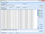
I got very excited when I used your code and got the following result.
pixy-hippy.jpg
However, the results were not quite as I expected, but after modifying your code and using the separate b variables of the w variables like so
Code:
symbol area = 0
setfreq m8

	Do

		SerIn 0,T4800_4, ($AA), b1, b2,b3, b4,b5, b6,b7, b8,b9, b10,b11, b12,b13

	Select Case b1
 	 Case $55 : SerTxd( "Normal")
  	Case $56 : SerTxd( "Color")
  	Else     : SerTxd( "Unknown")
	End Select

		SerTxd(" Signature= ",#b5)
		SerTxd(" X= ",#b7)
		SerTxd(" Y= ",#b9)
		SerTxd(" Width= ",#b11)
		SerTxd(" Height= ",#b13)
		'SerTxd(" Area= ",b0)

		SerTxd( CR, LF )

Loop
I get the following results with values as I expected.
pixy-hippy2.jpg
Now my problem is I need to work out the area using the height and width, but seem to be unable to get it right, as I am not allowed to multiply #b11 by #b13 for some reason. Any ideas?
Once I can do this, I can tell my robot when it is getting too close to an object that it is (hopefully) following.
As requested, here are some links in case other people wish to see it.
Porting guide for Pixy [url]http://www.cmucam.org/projects/cmucam5/wiki/Porting_Guide [/URL] I am using UART.
Arduino porting http://www.cmucam.org/projects/cmucam5/wiki/Hooking_up_Pixy_to_a_Microcontroller_(like_an_Arduino)
Datasheet and Documents page http://www.cmucam.org/projects/cmucam5/documents
Many thanks for all your help. (I do feel, though, that I am getting too old to be learning all this stuff) :D
 

hippy

Technical Support
Staff member
With SETFREQ M8 and T4800_4 you are probably using 9600 baud so it's best to change T4800_4 to T9600_8. Make that change first, check you still get the same results.

In your first screenshot, X=57600, Y=33792, which in hex is $E100 and $8400, so I guess the byte order was wrong. With -

SerIn 0, T9600_8, ($AA), b1, b3,b2, b5,b4, b7,b6, b9,b8, b11,b10, b13,b12

you should be able to go back to outputting the #w values and get the same results as using the #b values - Added: signature will probably become 257 again but we can sort that out later.

Calculating area should then work with "w0=w5*w6".

For your existing 'works with bytes' code, "w0=b11*b13".

Your error trying that might have been including the # signs which are only needed in the SERTXD commands or not using a word variable for area. You have a missing # in your SERTXD for "area" so it could have been that -

w0 = ...
SerTxd( " Area =", #w0 )

Have another go; we seem to be on the right path!
 
Last edited:

Kelpy

New Member
What an absolute star, Hippy :D. Works perfectly, apart from the signature number, but I'm not bothered with that at the moment.
Thank you so much - I've had sleepless nights and all sorts over this. Should have asked earlier, instead of spending weeks trying to suss it out myself. Thank you.
Just got to get to grips with writing a few routines to get the pan tilt to follow the blob and the motors to make sure the blob isn't too far away or too close.
I'll keep you posted with my results. May take some time, though.
Cheers.
 

hippy

Technical Support
Staff member
Glad it helped. I was quite surprised it did to be honest; I expected the possibility of timing issues with the serial.

From the porting guide it seems multiple consecutive $AA55/$AA56 sync words can be sent so may have got slightly lucky there.

http://www.cmucam.org/projects/cmucam5/wiki/Porting_Guide

Not sure how 'signature' works, seems to be $0101 (257) so you could use b5 or b4 which seem to both be 1 until that stops working :)

It would be a good idea to handle checksum verification and improve the code to only handle data it should be handling but you seems to be in a position where it works well enough to continue your adventures.
 

Kelpy

New Member
I'm afraid I'm struggling again :(
I'm using setfreq m8 so that my 28X1 will run at 8MHz so I can use 9600 baud to talk to pixy.
Whilst I've had some success in getting my bot to roll forwards or backwards as necessary, using motors, when the area of the object decreases or increases, I'm struggling in getting the camera to follow the object using pan and tilt, using servos.
Then I read in the manual that servos will not work when the 28X1 is running at 8MHz.
EDIT I realise I can just increase the time when reading pixy subroutine and then decrease when jumping back.
My question is, can I simply buy a 28X2 chip (which runs at 8MHz, I think) and put it in my 28 Project Board without consequences?
 
Last edited:

inglewoodpete

Senior Member
...Then I read in the manual that servos will not work when the 28X1 is running at 8MHz.
EDIT I realise I can just increase the time when reading pixy subroutine and then decrease when jumping back.
My question is, can I simply buy a 28X2 chip (which runs at 8MHz, I think) and put it in my 28 Project Board without consequences?
In it's day, the 28X1 was the PICAXE chip of choice. I used dozens of them. However, it had one or two shortcomings, especially when compared with the X2 chips, and there were many ingenious work-arounds as you have discovered.

The 28X2 is a far superior chip, which I have used to upgrade several projects (from 28X1). Some of the commands will change slightly - the programming editor will tell you when code needs changing. The most noticeable change will be the way pins are addressed. Refer to the X2 release notes, here.
 

hippy

Technical Support
Staff member
Switching to a 28X2 should get you servo control but SERIN can disrupt the servo loop timing. In this case you are receiving 14 bytes at 9600 and that will take 16ms, plus any waiting for each packet to be sent.

It may be easier to have the servo loop controlled by the SERIN timing, using PULSOUT rather than SERVO commands which should work on the 28X1. Not sure what happens though when there is no target detected.

You could possibly use the 28X2 background serial receive to run servos and handle packets but that could complicate things.

It may be easier to go to a two PICAXE solution with a separate PICAXE controlling the servos commanded on what to do by the master which receives the image data.
 

Kelpy

New Member
Thanks for that, hippy.
Good grief, I'm only just about getting my head around 1 picaxe, never mind 2.
I'l have a play with your suggestions.
I have 'sort of' got it working, using inc and dec for the servos with a few short pauses here and there, but it is quite jerky.
I'll try and learn all the timings etc.
Cheers.
 

Kelpy

New Member
Well, I have now got a 28X2 installed in my Project Board, which presumably will enable me to receive data at 19200 using setfreq (would this mean that my 14 bytes would be received in 8ms?) (The Pixy processes 50 frames per second, and 19200 is the default baudrate). Will this make any difference, or am I still going to have problems with serin and servo signals?
I've been trying to understand the timings etc, but find it very confusing. Do I need to work out some pause lengths (and where would I put them!) or use pauseus or something?
And how do I control the servo loop with pulsout so it works from the serin command.
Another question, if I use 2 picaxes (I do have another Project Board and another 28X2), and send date from no1 to no 2 (which would control the servos), am I not going to have the same problem with serin on the 2nd picaxe? Or would serrxd using the molex serial pin be any different? edit Although I suppose I will only have to send 2 values for the servo positions.
I'm sorry to ask all these questions, which at times must be dumb, but my brain doesn't work as well as it used to, but I'm determined to learn.
I have to say, though, it took me all day yesterday working out how to convert the Pixy positions into corresponding servo signals. Not helped by the fact that the picaxe only works in integers. It's been a very long time since I did any maths:D
 
Last edited:

hippy

Technical Support
Staff member
You can try increasing PICAXE operating speed and using 19200 baud. Whether it works really depends upon the camera and what its inter-byte gap timings are. If it doesn't work reliably just back it down to 9600 which we know does.

A shorter time for receiving data will likely improve servo timing but may not necessary resolve all problems.

One thought - if you have SERVO commands rather than SERVOPOS, consider moving to SERVOPOS with just initial SERVO commands for each to initialise the servos. That may make things less jerky.

With a second PICAXE you would not have to use SERIN but could use background serial receive. Without blocking you should be able to get much better servo control either using SERVOPOS commands or your own servo timing loop.
 

Kelpy

New Member
Hello again, all you experts. I have another stumbling block.
As per hippy's suggestion, I now have 2 picaxes hooked up, both of which are 28X2, with the idea of collecting the data from Pixy, using serin, with picaxe 1, and running the servos from picaxe 2. The transmit code from picaxe 1 is
Code:
serout c.1,T9600_8, (b1,panpos,tiltpos)
, using a lead from c.1 to the serial in pin on the molex connector on picaxe 2.
The code for receive is
Code:
getdata:

	disconnect
	
	hsersetup B9600_8, %00
        hserin[100,getdata],0,3 
	ptr=0
	get 0,b1
	get 1,panpos
	get 2,tiltpos
		
	reconnect

return
The problem is I am not receiving data, and I suspect it is to do with the mode of hsersetup (I find it very confusing, although it is probably quite simple once you understand it).
Can anyone point me in the right direction.
edit By the way, hippy, I am using servopos after the initial servo command.
 
Last edited:

hippy

Technical Support
Staff member
Not sure why you have the DISCONNECT and RECONNECT commands in there but it may be because you were expecting data to come in on the Download Serial In. That is not correct. On the 28X2 the HSERIN serial input is pin C.7, leg 18.

It would probably be worth putting your existing code to one side, create simpler test code to get the two PICAXE talking. Start with sending just a single byte, check you can receive that ...

Code:
Do
  SerOut ... ( "A" )
  Pause 1000
Loop
Then incrementing values ...

Code:
Do
  For b0 = "A" To "Z"
    SerOut ... ( b0 )
    Pause 1000
  Next
Loop
Then move on to more values ...

Code:
Do
  For b0 = "A" To "X"
    b1 = b0 + 1
    b2 = b0 + 2
    SerOut ... ( b0, b1, b2 )
    Pause 1000
  Next
Loop
 

Kelpy

New Member
Ok, I have managed to get the 2 picaxes talking to each other, using your snippets above, with the expected results.
I have now also got picaxe 2 to receive the values for servo positions calculated by picaxe 1 , with expected results and displayed on the terminal.

Pan-position = 152 Tilt-position = 153
Pan-position = 152 Tilt-position = 153 etc etc

The problem I have is that when I try to put these values into servopos, everything goes awry. What am I doing wrong?
This is my code for Picaxe 2

Code:
symbol panpos=b2
symbol tiltpos=b3
symbol pan=2
symbol tilt=3

init:
	panpos=150
	tiltpos=150
	servo pan,panpos
	servo tilt,tiltpos

main:

	hsersetup B9600_8, %00
	hserin 0,3 
	pause 10
	
	get 0,b1
	get 1,b2
	get 2,b3
		
	panpos=b2
	tiltpos=b3
	
;			servopos pan,panpos
;			'pause 10
;						
;			servopos tilt,tiltpos
;			'pause 10
	
	ptr=0
	
	SerTxd( " Pan-position = " , #panpos )
	SerTxd( " Tilt-position = " , #tiltpos )
	SerTxd( CR, LF )
		
goto main
I have also tried it with the SerTxd commands disabled, to save time(?).
 
Last edited:

hippy

Technical Support
Staff member
The problem I have is that when I try to put these values into servopos, everything goes awry.
In what way do things go awry ?

It could be that HSERIN as used is actually blocking or is otherwise disrupting the servo loop timing. I don't know the answer to that off-hand.

You could try adding a longer PAUSE 100 in the program which will give the servo loop a better chance to run to see if that improves things though it may make it a little less responsive.

It could be that without a 'start of data' synchronisation the data for pan and tilt are getting corrupted or are being placed in the wrong locations. You could try adding a qualifier ...

HSERIN 0, 3, ( $FA )

SEROUT ... ( $FA, b0, b1, b2 )
 
Top