Dicky Mint
Senior Member
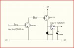
Hi I'm wondering if I can drive a 3.3V voltage regulator from a PICAXE pin via an NPN and a PNP transistor?
The Picaxe outputs use FETs so you should be able to parallel them without ill effects. Each pin can drive ~20mA, so three of them driving the regulator would suffice. (Total current out of all Picaxe pins may not exceed ~100mA however!). That way the Picaxe could supply the regulator directly. No need for transistors etc.I'm looking at a ball-park figure of 50mA so out of range of the PICAXE pin
In a perfect world, with no possibility of program error, I would agree.The Picaxe outputs use FETs so you should be able to parallel them without ill effects
I don't think this is the most difficult task imaginableIn a perfect world, with no possibility of program error, I would agree.
") And of course you would test it with open outputs before hooking up the regulator and attempting to draw maximum current.
And of course you would test it with open outputs before hooking up the regulator and attempting to draw maximum current.Thats true, lots of stuff is more difficult.I don't think this is the most difficult task imaginable
Yep, the only sensible way to go.But personally, I'd Keep It Simple and Safe with a single PNP transistor.