I have a simple 20m2/EEPROM data logger powered with 3 AA batteries (max 4.5 vdc). Power is turned ON with a latching PB switch. When the data logging mission is completed I want to have the 20m2 power itself down (shut the 5vdc OFF). My searches have turned up several ideas. Any elegant ideas from the FORUM for the best way to do this with minimum components? Thank you in advance. Jims
Picaxe power itself down
- Thread starter jims
- Start date
For the picaxe, there are micro-power states you can put it in that make the current draw very low. Other parts can be powered from the Picaxe output pins and thus turned off when needed. Checkout the Picaxe commands Nap and Sleep.
Microchip do a useful application note about power consumption, the reference isn't to hand but you will be able to find it. It is necessary to put the pins in the right minimum-power state to have the lowest consumption.
Microchip do a useful application note about power consumption, the reference isn't to hand but you will be able to find it. It is necessary to put the pins in the right minimum-power state to have the lowest consumption.
Hi,
The "brute force" method is a relay, but that's bulky, not power efficient, relatively expensive and strictly, needs an overswing protection diode, so involves two components. The smallest method would probably be an optocoupler (4 pins?), but that probably requires a resistor for the LED so still two components, inefficient and limited current capability.
For moderate currents in the PICaxe, then almost any CMOS gate package could control the supply or earth rail of the PICaxe. Cheap, but the gate package is likely to have 14 pins. For higher currents (e.g. if the PICaxe drives lots of LEDs) then a cheap NPN + PNP transistor pair and a few resistors could switch the PICaxe rail economically, but obviously not a minimum component count.
However, all these "solutions" require one or more additional components wired across the battery. So, as geoff has already said, in most cases it's probably best to just keep the PICaxe connected to the battery and simply minimise its current drain with SLEEP and DISABLEBOD, etc. commands. Then wake it up with a power cycle.
Cheers, Alan.
Another thing to consider is phantom powering of the Picaxe. Even if you remove the supply voltage, if any of the input pins have a high signal applied to them, the Picaxe may very well continue to operate. The same would be true if the source were removed to power down the Picaxe. Then if any input pins have a low applied to them, the Picaxe may continue to operate. The phantom powering is a result of the connection of internal ESD diodes to the supply/ source rails. Even a pwm signal applied to an input pin can power the Picaxe ( and many other chips with ESD protection) if there is some capacitance ( bypass capacitor)
Putting the Picaxe to sleep will likely not consume any more battery power than the external components necessary to allow the Picaxe to turn itself off.
Putting the Picaxe to sleep will likely not consume any more battery power than the external components necessary to allow the Picaxe to turn itself off.
Hemi345
Senior Member
Lots of suggestions and links in the following thread:
http://www.picaxeforum.co.uk/showthread.php?22601-circuit-help-momentary-switch-for-power-on-picaxe-to-power-off/
If you're into using surface mount stuff, the MIC2005A is a handy little device that needs only a few external components (pull down resistor on ENABLE pin and decoupling capacitors). Use your push button to momentarily bring the ENABLE pin high on the MIC2005A, then program the PICAXE to hold that same pin high till you want to power it off. I've used these in a couple low-power projects (<500mA) and they work well.
Thank you for the suggestions. Not quite sure what approach I'll use. Have tried measuring the current with and without the "sleep" command. I have only a cheap meter and it reads about 7.2 ma without "sleep" and about 6.9 ma with "sleep". Not a large difference. Is this about what I should expect? Jims
The cheap meter won't do and is more than likely giving erroneous readings. It is not reasonable to expect a $5.99 meter from WalMart or Ebay to accurately read current in the microamp range, if it can even read that low.
You can test the meter by putting it in series with a 5v source across a 100K load to ground. It should read ~ 50 microamps. If it can't do that then it is worthless for testing Picaxe sleep current.
When measuring the Picaxe current, there should be nothing connected to the Picaxe I/O pins. No LEDs, no inputs, only a high value resistor from the serin pin ground to prevent it from floating. Disconnect the Programming Adapter when testing.
Exactly. And assuming PICAXE SLEEP is like PIC SLEEP it doesn't mean every internal peripheral and I/O is switched off.
You will have to switch off your I/O and (internal) PIC peripherals to get the most out of power saving in SLEEP.
A micropower design relies on the user designing the whole circuit as a micropower circuit.
The 2-MOSFET power control can offer sub-microAmp consumption, but if some other part of your circuit is doing something then all the gains may be lost.
This same technique can be used before regulators where applicable too.
It would be a good idea to post your circuit so people can offer suggestions and advice.
And remember, multimeters in uA mode can put a significant resistance in series with the load they are measuring.
Thanks to all of you. Actually Goeytex, my meter is better than a $5.00 Walmart job. Using my meter I measured 4.5vdc (3 fresh AA batteries) and with a 100Kohm resistor it read about 43 microamps. Was hoping to see the effect of the "sleep" command on my circuit board. Put together this routine hoping to use it on my board, but from the comments, I guess that I can't do it.
Not sure where to go from here. Maybe the "brute force" approach with relay.Jims
Code:
[color=Green]'******************************************************
'*** Picaxe 20m2 using Jims data recorder board.    ***
'*** Measure current draw when use "sleep" command. ***
'******************************************************[/color]

[color=Blue]symbol rled[/color][color=DarkCyan]=[/color][color=Blue]B.6     [/color][color=Green]'Bi color LED.[/color]
[color=Blue]symbol gled[/color][color=DarkCyan]=[/color][color=Blue]C.2     [/color][color=Green]'Bi color LED.[/color]

[color=Navy]#picaxe [/color][color=Black]20m2


main:
    [/color][color=Blue]do
     high rled  low gled  [/color][color=Green]' Turn red LED ON.
     [/color][color=Blue]sleep [/color][color=Navy]2              [/color][color=Green]' sleep for 4.6 seconds
     [/color][color=Blue]low rled high gled   [/color][color=Green]' Turn green LED ON.
     [/color][color=Blue]pause [/color][color=Navy]5000           [/color][color=Green]' Pause 5 second.
[/color][color=Blue]loop[/color]If you can have a bit of patience I can draw you up a circuit to try.
Do you have a PNP and a NPN transistor on hand ?
Do you have any diodes ?
What is your idea of minimal components?
Can you post a schematic ?
Do you have a budget ?
Hate to see you brute force a relay that could consume more power when on than it will save when off.
Do you have a PNP and a NPN transistor on hand ?
Do you have any diodes ?
What is your idea of minimal components?
Can you post a schematic ?
Do you have a budget ?
Hate to see you brute force a relay that could consume more power when on than it will save when off.
Umm... am I reading right?
Turn Red LED on, Green LED off.
Sleep
Turn Green LED on, Red off.
Where are you measuring current?
Are you including the current to the Red & Green LEDs in your measurement?
And like I said before you have to switch off all the PIC peripherals to maximise power saving in Sleep.
Just say if that makes no sense.
And if you post your circuit as it stands it may help save us all a game of ping-pong")
Turn Red LED on, Green LED off.
Sleep
Turn Green LED on, Red off.
Where are you measuring current?
Are you including the current to the Red & Green LEDs in your measurement?
And like I said before you have to switch off all the PIC peripherals to maximise power saving in Sleep.
Just say if that makes no sense.
And if you post your circuit as it stands it may help save us all a game of ping-pong
What Dippy Said,.
Also, Hemi Mentioned the Micrel devices that are excellent. However they are SMT and may be a pain to solder or place on a board. There are other similar devices in DIP such as the TPS2030 family from TI. One of these can drive the entire circuit and assure that the entire circuit draws ~ 10 microamps or less when off.
Also, Hemi Mentioned the Micrel devices that are excellent. However they are SMT and may be a pain to solder or place on a board. There are other similar devices in DIP such as the TPS2030 family from TI. One of these can drive the entire circuit and assure that the entire circuit draws ~ 10 microamps or less when off.
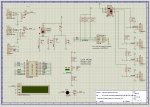
Thank you. I'll attach the schematic of my board. The data logger is located at an unattended location (serviced every 2-3 days) and if "feasible" I would like to power it down when the logging mission has ended. At this point I'm just trying to get an idea of the delta power savings (total power to the circuit board from the 5vdc supply) when using the "sleep" command or not using the "sleep" command with my circuit board.
Here's the circuit which works for me and performs the data logging that I want. Thanks again. Jims
Here's the circuit which works for me and performs the data logging that I want. Thanks again. Jims
Attachments
-
 211 KB Views: 58
Hemi345
Senior Member
Placing the npn and pnp transistors between your power source and all peripherals, would allow you to power everything up and down using your existing push button.
Have a look at this thread
In my example schematic, I'm demonstrating multiple pushbuttons that can power on the project and can control some aspect of the project.
Have a look at this thread
In my example schematic, I'm demonstrating multiple pushbuttons that can power on the project and can control some aspect of the project.
Yep, a lot of stuff that needs to be switched off there.
For one circuit I did, I used sleep mode on a 28X2.
The circuit had a radio chip with a wake up timer, which after the 28X2 was put into a 'sleep 0' state woke it up after a preset time (seconds to months) with an interrupt.
Current consumption in sleep was 18uA, but it took a while to arrange the circuit to stop stuff leching power, the peripherals (GPS in this case) were switched off with a MOSFET.
If you post your circuit you may get some additional ideas that you can use. Otherwise, this is mostly theoretical. A PIC with correct I/O states can run on very low power. Most likely, with suitable arrangements, a Picaxe can do similar. The key is what the rest of the circuit is doing, and how can that be controlled by the Picaxe.
Attached is a circuit that I have used in the past with good results.
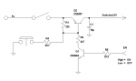
To start the logger, press the momentary switch. At the beginning of the code put a high on the Picaxe output pin going to EN. This latches the switched 5V on and keeps it on when the SW is released. When the logging is done, the code needs to tell the Picaxe Pin attached to EN to go Low. The entire circuit will power off. The circuit can only be powered back on by pressing the switch again. When the circuit is powered down, the only current will be leakage current and should only be a few microamps.
The toggle switch is so that the board can be turned off manually.
The switched 5V operates the entire board/ not just the Picaxe. The 2N2907 is good up to about 600ma of current, I suspect your board will use a lot less than that.
I just tested this on the bench and it works fine.
Good Luck
Attachments
-
 13.3 KB Views: 49
Last edited:
It would be interesting to see how well it works without Q1 and R5.I just tested this on the bench and it works fine.
Take the bottom of R2 to a PICAXE pin, set that pin output LOW at the start of the program then use an INPUT or HIGH to power itself off.
You can probably replace R4 with a zero-R wire as well.
Great,A DIP latching relay is small, bulletproof, makes for complete disconnection, zero voltage drop, and zero power consumption except a brief pulse at power off. Battery powered home thermostats get over a year out of 2x AA batteries.
Do you have a part number ?
Hi,
I think the two transistors are essential, because when the PICaxe is "off", the switch transistor is "outside" of its supply rails, so otherwise a pin protection diode would turn the switch transistor back on again.
However, a few simplifications might be possible: Firstly, save R4 by putting the pushbutton directly across Q1 (collector to emitter). Also R5 could be zero ohms by using a "Weak Pullup" resistor within the PICaxe. Particularly useful with the "Input Only" pin (Leg 4 on M2s) because it can't accidentally deliver too much current.
In cases when Q1 and Q2 are never likely to get "hot", R1 could also be omitted because it's only required to prevent amplification of (thermal) leakage currents. So potentially just 3 components (excluding the switch and decoupling), 8 pins/legs and perhaps 20 cents (or pence).
Cheers, Alan.
Yes, Goeytex's design in #18 is basically what I hinted at in #3, and is what I would use (with "European" style BC548/558/327/337 transistors).Attached is a circuit that I have used in the past with good results.
I think the two transistors are essential, because when the PICaxe is "off", the switch transistor is "outside" of its supply rails, so otherwise a pin protection diode would turn the switch transistor back on again.
However, a few simplifications might be possible: Firstly, save R4 by putting the pushbutton directly across Q1 (collector to emitter). Also R5 could be zero ohms by using a "Weak Pullup" resistor within the PICaxe. Particularly useful with the "Input Only" pin (Leg 4 on M2s) because it can't accidentally deliver too much current.
In cases when Q1 and Q2 are never likely to get "hot", R1 could also be omitted because it's only required to prevent amplification of (thermal) leakage currents. So potentially just 3 components (excluding the switch and decoupling), 8 pins/legs and perhaps 20 cents (or pence).
Cheers, Alan.
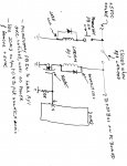
Sure a lot of good ideas. Think that I'll try erco's suggestion using a Panasonic TN2-L2-5V latching relay with a MOSFET and a few other components that I have and experiment using the attached schematic (sorry about the quality of the schematic). When it's working it should disconnect the power source completely. Comments please. Thank you JimsA DIP latching relay is small, bulletproof, makes for complete disconnection, zero voltage drop, and zero power consumption except a brief pulse at power off. Battery powered home thermostats get over a year out of 2x AA batteries.
Attachments
-
 337.3 KB Views: 26
Perhaps I am missing something, but why would you need any external components? If everything is powered from the same 4.5v battery, power those external things that need power from a Picaxe output pin (20mA available per pin). Then turn them off before sleeping the Picaxe (with disablebod). Turn on with an n/c button that interrupts the supply and causes a reset, or by occasional wake-ups to look for a suitable signal.
http://ww1.microchip.com/downloads/en/DeviceDoc/01146B_chapter 2.pdf
Not everything here is accessible from a Picaxe but you should be able to get a battery life measured in years (close to shelf life) by following the advice in the note.
http://ww1.microchip.com/downloads/en/DeviceDoc/01146B_chapter 2.pdf
Not everything here is accessible from a Picaxe but you should be able to get a battery life measured in years (close to shelf life) by following the advice in the note.
erco
Senior Member
There are a few 3V latching relays on Ebay: http://www.ebay.com/sch/i.html?_from=R40&_sacat=0&_nkw=3v+latching+relay&_sop=15
Here's a 4.5V: http://www.ebay.com/itm/2-pcs-4-5-Volt-Latching-Relay-2-Form-C-DPDT-TXD2-L-4-5-/110469523543?pt=LH_DefaultDomain_0&hash=item19b87f2857#ht_2194wt_873
A momentary SPST switch can be used to manually turn the relay on, and one uC pin can be used to turn it off, even driven directly by a microcontroller pin. One benefit of latching relays is that since they take only a brief pulse to trigger, you can safely pull a little extra current out of an I/O pin for ~200 milliseconds.
I bought some 5V Aromat latching relays back when Electronic Goldmine blew them out for a buck. They are long gone now. They work fine on 3.3V. They are unusual in that they have a single, reversible polarity coil. One polarity sets the relay and the opposite polarity resets it. Most other latching relays have two seperate coils & pin connections. Pulsing one pin sets the relay, another pin resets it.
I/0 Budget for one thing. Looking at the schematic, I don't see enough spare I/0 pins to do as you suggested.Perhaps I am missing something, but why would you need any external components?
Also it has been my experience that powering certain devices from a Picaxe pin does not always work as expected with considerable (> 1V) voltage droop seen at the output pins with a 330R load. With a 4.5v supply that would be less than 3.5V available to the device. With a 5V supply, put a 330R resistor on a Picaxe I/O pin to ground. Take the pin high in code and measure the voltage at the Picaxe Pin. It will be ~ 3.8V.
A Picaxe output pin can handle up to 20 ma of current , but that does not mean that the output voltage is constant from 0ma to 20ma. It is not.
A DIP latching relay is small, bulletproof...
Is it entirely bulletproof ?One benefit of latching relays is that since they take only a brief pulse to trigger, you can safely pull a little extra current out of an I/O pin for ~200 milliseconds.
If the 'off' coil needs a 200ms pulse then what happens when the off pulse turns the power off before that 200ms elapses ?
I suppose the solution is to use large reservoir caps to keep the supply up for as long as necessary after the relay disconnects power.
Thanks, I think we're getting there. Goeytex, the schematic in post # 14 shows that there are 2 unused ports (C.4 & C.5). Should be enough. I'm using C.4 for this as shown in my ugly hand drawn schematic in post #24. As I interpret the data sheet for the Panasonic relay P/N TN2-L2-5V; the relay will unlatch with a shot of 40 milliamp for 2 msec. I plan to experiment with all this once I get the hardware. Will try hippy's idea for a large reservoir cap if necessary. Erco, thanks for the relay source info. Also, have you actually built and used this?
Jims
Jims
erco
Senior Member
Certainly some experimentation is in order for any particular relay, controller, and power supply combination. OP jims has 4.5V to play with. 3V relays are available for direct drive if the I/O pin has much internal resistance, or a switching transistor could be used, which is the "best practices" option. I have built and used these several times using direct drive without incident. A PicAxe I/O pin rated for 20 mA continuous duty can reliably deliver more than that for a few milliseconds, and/or two outputs could be ganged per another discussion here. Definitely use a flyback/freewheeling diode across the relay coil.
I saw two spare pins (easily with 40mA available), and a bunch of potential dividers and pull-downs all with 10k resistors (thus drawing under 500uA each, mostly intermittently) and some 4.7k pull-ups. Nothing there to worry an output pin. Plus an eeprom and some sensors, which I assume will need a few mA each. And if there were to be a small drop, so what? The eeprom could be a 3.3v type, and perhaps even the sensors. The display might be an issue but this is a datalogger so generally unattended, so the display isn't needed most of the time, it could have a pushbutton all of its own if necessary.Looking at the schematic, I don't see enough spare I/0 pins to do as you suggested.
A Picaxe output pin can handle up to 20 ma of current , but that does not mean that the output voltage is constant from 0ma to 20ma. It is not.
So I maintain (at least until someone does the actual calc for the situation in question), that all the external components might be avoidable.
premelec
Senior Member
Apropos erco's suggestion I just got a catalog in the mail today [retro!] from www.allelectronics.com showing a surface mount 5VDC 250 ohm single coil DPDT latching relay for $1. their cat# RLY-565 . Note that these would be latched and unlatched by reversing polarity on the coil - could be done with 2 pins or external circuitry.
With a 20M2 supplied by a well regulated 5.V supply and one 330 ohm resistor from an I/O pin to ground, when the I/O pin is taken high the voltage at I/O pin is ~3.8v. The current through the resistor is (3.8V / 330R) or ~11.5ma.
With a 330R resistor in parallel with a 1K resistor (248R) the I/O voltage is remained at 3.8v. Therefore the current through the resistor is (3.8V / 248R or ~ 15.3 ma.
Any reduction of resistance from about 220R resulted in a further drop in voltage and no increase in current above 15.5ma.
I could not get the I/0 pin to supply > 15.5ma regardless of resistance. (Using Pin c.0)
By paralleling 2 output pins the I/O voltage was ~4.3V with a 248R load. ( ~17.3ma)
The Picaxe supply voltage remained stable at 4.99V throughout testing.
Goeytex, that is most fascinating and an aspect that I had not previously considered. My interest is in driving optically-coupled solid-state relays. I am using a few of these with direct drive from the PICAXE output and the current is the determinant in driving the optical MOSFETS properly. I had done the calculations on the 5 volt /25mA max basis that I got from the Microchip datasheet, but I will now have to go and take some measurements to check that I have the correct resistors in place; at first glance your findings suggest that I do not have the correct values. Thanks for this info; I wonder how it applies across the other PICS apart from the 20M2? Also, is this the same for all the I/O pins on the chip? - you do not specify which pin you tested.
@Circuit
My tests were done with a 20M2 and Pin C.0. No other pins were tested. The resistors were 1%. The components were on a breadboard.
Please post your results with the SSRs. The Picaxe should have no problem with the SSR's as most of these operate from 3-32V at a minimum
current. Many SSRs have an internal series resistor so no external resistor is required.
A new thread may be appropriate.
premelec
Senior Member
@Goeytex - thanks for the empirical data - I wonder if 'all' the PIC pins have similar current drive / sink behavior... I admit to not having used any higher currents from PICAXE pins - I've used external drivers. It would appear that the 20ma pin current might be into a short... with internal current limiting. perhaps technical could give more information on this. Perhaps a note in Manual 3 would be appropriate [if not already there].
That's useful testing.
It's interesting to look at PIC data sheets to see the currents involved when they (Microchip) define Voh and Vol.
Any semi of that construction is going to have a resistance in the driver so it's not surprising that V droops as I increases - cf a tiny MOSFET, but it's handi to know how much. There won't be any pukka full-blown current limiting.
Maybe if Goeytex is feeling keen he can produce a graph (hint hint).