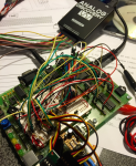
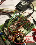
Axe110 data logger question

I am attempting to understand the axe110 datalogger and have hit a snag. I have the unit functioning using two ds18b20 temp sensors and a ldr and everything appears to work ok and save the data using the pause function for my timing. I recently purchased some ds1307 rtc from germany and i am having some difficulty trying to make the logger work with the rtc. I have inserted the rtc and battery and run the wizard to pre-program the time but when i attempt to set my timing to rtc in the data logger wizard although it programs ok i get no activity after the first intitial save. Is there a easy way to check that the rtc is actually programmed and working on the data logger board, i purchased 5 of these and have tried with 2 but same results.
 

oracacle

Senior Member
how long delay are you programming? i would thin that less than a second could cause and.

also the the wizard for setting the rtc does seem to have a check for making sure that it is set. the only change that i would make to the programme would be to add
Code:
#terminal 4800
pause 500
at the begining of the programme. this will automatically open the terminal window to allow you to see if it has been programmed. also setting the 1hz led flaash will give a fairly clear indication of the correct programming of the clock IC too
 
Thanks for the reply, with the terminal set i can see if the rtc program fails or passes. I have now discovered the problem is with the battery i have fitted, if i program the rtc with the battery on the board it fails but if i remove the battery it programs ok and starts logging at the correct interval. The battery is one that came with one of the cheap tiny rtc modules and works ok with this. It is marked as LIR2032 and a quick voltage measurement with no load on the battery is 4.4 volt and not just over 3.6 as i expected. Is this maybe something to do with it being slightly higher than the logger voltage of around 4.2 ?
 

oracacle

Senior Member
i beleive that the rtc should only need a 3 volt backup battery, some thing like a CR2032. but it would sound as though you have found the thing that was causing your issue.
 

geezer88

Senior Member
From the voltages you posted, my bet is the LIR2032 is a rechargeable lithium ion of some sort.
tom
 

westaust55

Moderator
The back up battery must have a voltage of <= supply voltage /1.25

If the supply voltage falls to or is less than battery voltage * 1.25 then the Ds1307 goes to backup mode and does not accept i2c commands.
This is explained in the Ds1307 Datasheet.

Also the min operating supply voltage for the DS1307 is 4.5 volts.
It may well operate at slightly below but it is not in spec and may caus grief.
 
Thanks for all the replies, i understand a little more now and every piece of knowledge is useful. I have my logger working now with the rtc just waiting for new batteries to be delivered. Now i can start with my little project that is to log some temperatures from a swimming pool i.e the water temperature and the outside air temperature. I have used the logger wizard to generate the initial code but need to make some mods to suit what i want as follows:-
I wish to send the temps via a axe213 rf board to a receiver to display them, when a time is specified in the logger say everyday at 12pm take readings then the program loops round the wait_for_time_match until the correct time is read. What i propose to do is add a gosub back to read_sensors and then use the lcd output pins to connect to my axe213 and send the two temps is this ok ?
Second you can only download the data once the mission is complete, is it ok to add a button or something that will take me directly to read_init to allow me to look at / download the data whenever i want before the mission is complete ?
My last option would be to save the day and month along with the temps for easier reading of the data later, I have not looked into this yet but did notice a post for the logger with date stamping by westaus55 which i will take a look at.
I am not asking for code to do this as i will attempt to have a go myself if it is possible
 
I have now tried my first data logger mod from the original wizard program where i am attempting to update the LCD display (eventually going to use the axe 213 to send the info to a remote display). I have inserted three lines of code into the wait_for_time_match sub that basically reads the temps again and then calls the lcd display update before returning to check the preset logging time. Although this seems to work ok can anybody tell me if i am likely to cause problems elswhere by doing this before i move onto my next mod.
My code change to the original wizard code is as follows:-
Code:
[color=Black]wait_for_time_match:
        [/color][color=Green];Following three lines added to give actual temperature readings while
        ;waiting for the logging interval
        [/color][color=Blue]readtemp C.1[/color][color=Black], [/color][color=Purple]data1                 [/color][color=Green]; added read Pool Temp to update lcd
        [/color][color=Blue]readtemp C.7[/color][color=Black], [/color][color=Purple]data7                 [/color][color=Green]; added read Air Temp to update lcd
        [/color][color=Blue]gosub [/color][color=Black]display_on_lcd                [/color][color=Green]; Call display and update readings
        ;End of LCD update
        [/color][color=Blue]sleep [/color][color=Navy]10
        [/color][color=Blue]hi2csetup i2cmaster[/color][color=Black], [/color][color=Navy]%11010000[/color][color=Black], [/color][color=Blue]i2cslow[/color][color=Black], [/color][color=Blue]i2cbyte
        hi2cin [/color][color=Navy]0[/color][color=Black],[/color][color=Blue]([/color][color=Purple]secs[/color][color=Black],[/color][color=Purple]mins[/color][color=Black],[/color][color=Purple]hours[/color][color=Black],[/color][color=Purple]temp_byte[/color][color=Black],[/color][color=Purple]day[/color][color=Black],[/color][color=Purple]month[/color][color=Blue])
        [/color][color=Green];if alarm not correct just loop
        [/color][color=Blue]if [/color][color=Purple]hours [/color][color=DarkCyan]<> [/color][color=Navy]$12 [/color][color=Blue]then [/color][color=Black]wait_for_time_match
        [/color][color=Blue]if [/color][color=Purple]mins  [/color][color=DarkCyan]<> [/color][color=Navy]$00 [/color][color=Blue]then [/color][color=Black]wait_for_time_match
        [/color][color=Blue]return[/color]
 
Thanks Technical, now i see if i can make a mod so that i can download the data at any time without waiting for the mission to complete.
 

Arthurb

New Member
I have put togetr the axe110 logger on my axe091 dev board, where the ds1307 is already available, and all is working as expected except that the logging intervals are far shorter than they should be.

The 1Hz led flash after setting the timer is also much much faster (probably 20Hz ).

I looked through the code but cannot find why the ds1307 is doing this, other than perhaps the frequency of the watch crystal. The axe091 data sheet tells me that it should have a 32.768kHz crystal on board, but the Axe110 datasheet does not specify what frequency the crystal should be?

I did not make any changes to the wizard programs and i am using an 18m2.

Any pointers will be appreciated please.
 
Last edited:

westaust55

Moderator
By default, the 18M2 operates at 4 MHz.
There is no 32 kHz crystal on the AXE091 board (to my recollection) for the PICAXE chips.
Does your program have a SETFREQ command included? If so what value has been used?

Maybe also post the actual code you have downloaded so folks here can review for any reason why your project is operating at 20 or maybe 16 times faster than expected.
 
Last edited:

Arthurb

New Member
Good day people

My axe091 came with crystal soldered in place and I cant see what its details are (dont want to bend it)

There are no setfreq commands in the code (its the standard code generated by the wizard).

Maybe technical can let us know what crystal is installed on the axe091 - I bought mine a month ago.

Something else I found odd is that the "select 1Hz led flash" when initializing the ds1307 does make a difference (i.e. if left unchecked in the wizard, the led stays off, if I check it, it flashes quite a lot faster than 1Hz).

I also cannot get to the ds1307 directly as mentioned in the axe110 pdf, I need to copy code first into new bas file and send. This code does not have any flashing interval coding for the led ?

Im convinced the ds1307 is not initialized correctly.
 

Attachments

Last edited:

eggdweather

Senior Member
It's a 32.768Khz standard watch style xtal for the DS1307 clock chip. There are no adjustments that can be made in software. You can find these for sale just about anywhere and thereb-by details, but to be honest even with details you won't be much the wiser, accuracy is not always great, but stability of these crystals is about +/-50ppm, prabably good for about 10-20secs/month.

The data sheet on page 8 gives some more detail.
 

Arthurb

New Member
It's a 32.768Khz standard watch style xtal for the DS1307 clock chip. There are no adjustments that can be made in software. You can find these for sale just about anywhere and thereb-by details, but to be honest even with details you won't be much the wiser, accuracy is not always great, but stability of these crystals is about +/-50ppm, prabably good for about 10-20secs/month.

The data sheet on page 8 gives some more detail.


Thank you for this - Im getting the feeling that the ds1307 is just not worth all the fiddling for what I want to do - sampling intervals of a few seconds to a few minutes.
 

hippy

Technical Support
Staff member
The watch crystal fitted to the AXE091 will be suitable for the DS1307 it is intended to be used with so should be working as expected.

It may be worth running some short test code to check that the DS1307 is working as expected.
 

Arthurb

New Member
Thanks to all of you for responses - will play with the ds1307 a bit more to see if I can find the problem, but my immediate needs to get a data logger working is answered for now.
 

eggdweather

Senior Member
Unless you want highly accurate timing, I think the DS1307 will be ideal for your intended data logging application. Getting time or secs or minutes from it is really easy and so determining data logging intervals quite straightforward.
 

westaust55

Moderator
Two aspects which will prevent a DS1307 from running:
1. If bit7 in the seconds register is set (as in default when first energized) holds/stops the clock running
2. If no backup battery is connected then The battery pin must be tied to ground/0 volts.
 

Arthurb

New Member
I determined that the DS1307 runs 6 times faster than it should - so another work-around is to simply consider that when selecting time intervals from the wizard. (selecting 1 minute sampling interval results in 10 seconds actual delay)

But I will investigate what is behind it in any case
 

hippy

Technical Support
Staff member
The DS1307 is clocked only by its crystal so it should not be possible to run at six times the expected rate. There is either a hardware issue or perhaps some flaw in the way time is being tracked. It could be that the base unit of time period used in the code is 10 minutes rather than one minute.

How did you determine things are running six times faster ?
 

Arthurb

New Member
Good news, I bent all the wires connected to the WP, SDA,SCL and OUT connectors near the crystal out of the way of the crystal, it still did not resolve the problem, then I just pushed on the crystal to flatten it on the pc board (it was standing up at about 6 degrees from horizontal) - and voila - led flashing at 1 Hz - I expect the problem to be solved - will test.
 

Arthurb

New Member
Youre probably right Texas - will check it, the axe091 is stock standard as I received it with crystal already in place (not my soldering is what Im trying to say :)
 

techElder

Well-known member
The AXE091 is the greatest prototype gadget I've ever had. Right now I have a project running that uses a 40X2, 20X2 and 18M2 all having separate functions and connected to extra hardware on the protoboard. The DS1307 and 24LC16 have been activated, too. The lights, switches and pot have come into play.

I can forgive a little cold solder joint! :)
 

hippy

Technical Support
Staff member
Crystals are physical devices so it could be that it's suffered some kind of shock whilst in transit which knocked it out of kilter. Giving it a push may have put it back into shape. It would still be worth having a check of the solder joint at some point, even just to reassure yourself it is okay.
 

rmeldo

Senior Member
Hi,

sorry to interject the discussion. I am trying to determine whether it is possible to install and read/write the 24LC512/P I2C EEPROM (64KB) directly onto the AXE 110. The manual and wizard only refer to the 256 chip, but the 521 would suit me better.

Could anyone answer or point me to threads or literature?

Many Thanks
Riccardo
 

hippy

Technical Support
Staff member
24LC512 I2C EEPROM's should be electrically compatible with the AXE110, usable and read/write accessible by the PICAXE.

The Data Logger Wizard will however only generate mission code for up to 32KB devices. If you write your own code there should be no problem accessing the full size of the 64KB I2C EEPROM.
 

hippy

Technical Support
Staff member
Yes; 'i2cread' and 'i2cwrite' are deprecated but are just synonyms for 'hi2cin' and 'hi2cout'.
 

techElder

Well-known member
Shhhhhhhh!


Don't tell RevEd that a PICAXE programmer needs a power switch to perform a hard reset about every time it is programmed with a "real" program! Shhhhhhhh!
 
Top