JamesWhite
New Member
Hello everyone,
I have been working on a 5x7 led matrix project.
I saw a neat necklace in Nuts and Volts & on Hack A Day, and I thought I'd give it a go with a picaxe 20m2.
http://hackaday.com/2012/10/12/led-matrix-pendants/
Well I got it all built here are some pics...
Freeform!!!
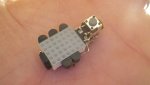
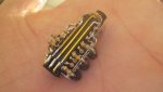
Unlike the 'tinymatrix' I am not directly connecting the matrix to the pins of the picaxe. I do not have a final schematic, but I used 120 ohm resistors from the matrix rows to the picaxe pins and 2222 npn's for the columns w/ 4.7k base resistors.
Now for the issue that I am hoping someone can shed some light on (hah that was a bad pun).
I wrote this code and upon powering on, column 5 did not light. I looked at my soldering closer and discovered what I thought to be a missed solder joint from column 5 transistor to the matrix pin. I had just enough room to fit my iron in there to solder it. Upon powering on again column 2 lights up along with column 5 simultaneously and vice versa. I have looked for solder blobs, and other problems but am coming up empty handed.
I am wondering if somehow the matrix is shorted out inside? Has anyone had that happen before? If anyone has an idea or something that you think I should check... I greatly appreciate it.
Thanks!
I have been working on a 5x7 led matrix project.
I saw a neat necklace in Nuts and Volts & on Hack A Day, and I thought I'd give it a go with a picaxe 20m2.
http://hackaday.com/2012/10/12/led-matrix-pendants/
Well I got it all built here are some pics...
Freeform!!!
Unlike the 'tinymatrix' I am not directly connecting the matrix to the pins of the picaxe. I do not have a final schematic, but I used 120 ohm resistors from the matrix rows to the picaxe pins and 2222 npn's for the columns w/ 4.7k base resistors.
Now for the issue that I am hoping someone can shed some light on (hah that was a bad pun).
I wrote this code and upon powering on, column 5 did not light. I looked at my soldering closer and discovered what I thought to be a missed solder joint from column 5 transistor to the matrix pin. I had just enough room to fit my iron in there to solder it. Upon powering on again column 2 lights up along with column 5 simultaneously and vice versa. I have looked for solder blobs, and other problems but am coming up empty handed.
I am wondering if somehow the matrix is shorted out inside? Has anyone had that happen before? If anyone has an idea or something that you think I should check... I greatly appreciate it.
Thanks!
Code:
'Constants

symbol col1 = c.0
symbol col2 = c.3
symbol col3 = c.5
symbol col4 = b.5
symbol col5 = b.4

symbol row1 = b.2
symbol row2 = b.3
symbol row3 = c.4
symbol row4 = c.2
symbol row5 = c.1
symbol row6 = b.6
symbol row7 = b.7

symbol sw1 = c.6

'Directives

#picaxe 20m2

'Main Program

dirsB = %00000011
dirsC = %11000000

'setfreq m32

do


	high col1

	gosub scanrow

	low col1


	high col2

	gosub scanrow

	low col2


	high col3

	gosub scanrow

	low col3


	high col4

	gosub scanrow

	low col4


	high col5

	gosub scanrow

	low col5


loop


scanrow:

high row1
pause 100
low row1

high row2
pause 100
low row2

high row3
pause 100
low row3

high row4
pause 100
low row4

high row5
pause 100
low row5

high row6
pause 100
low row6

high row7
pause 100
low row7

return
Last edited:
