Is this a good mosfet to use with limited gate voltage swing?

wapo54001

Senior Member
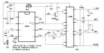
Please look at the attached schematic and the Fairchild mosfet datasheet attached.

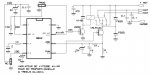
Normally, the mosfet would be tied directly to ground and the Picaxe would have a full 5V logic swing to control the mosfet. However, I want to measure the current flowing through the circuit, and I need the measurement to be referenced to ground, so I’ve put a current limiting/measuring resistor that drops exactly 2.0 volts at 13 milliamps of current (which is my selected maximum) between the source of the mosfet and ground. Thus, the gate of the mosfet is also referenced to a voltage above ground so the Picaxe has reduced congtrol of the mosfet gate.

Feedback to the Picaxe via an ADC pin allows the Picaxe to maintain the current at the level specified.

I have selected a mosfet (Fairchild BS270, datasheet attached) which I believe is a good choice to use in this situation where available gate swing is much less than 5V. Could someone confirm that my choice looks right? Or if I’m missing an important consideration and this won’t work, better to know it now before I go off on an unworkable tangent. Thanks in advance.
 

Goeytex

Senior Member
Doesn't seem likely to me that the gate voltage will be sufficient to adequately drive the MOSFET given a 154R current sense resistor. I would suggest reducing the current sense resistor to 50 Ohms and then add a 100 ohm resistor to the high side. This will give about a 4.0v gate drive, but the sense voltage will be reduced to about 500mv. Not a problem if you use READADC10 and use ADCCONFIG AND FVRSETUP to set the ADC reference voltage to be 2.048V. 500mv will give an ADC10 reading of about 250. More than enough to work with.

You will need to add a low pass filter ("Poor Man's DAC") between the sense resistor and the ADC input.

Do you know what you are getting into here ? Feedback loops are not easy to control
 

inglewoodpete

Senior Member
A bit more information would be helpful. You mention 13mA for the ADC calibration but what would the maximum current that the MOSFET would be expected to carry?

Edit: I see you are using (the same?) 5v supply for the MOSFET. Perhaps you would be better off using a P-channel MOSFET. That way you can put the gate all the way to 0v to turn the MOSFET fully on.
 

Goeytex

Senior Member
Given the 5V supply in the schematic, and the fixed resistance of ~154 ohms, the max current (100% Duty Cycle) could never be more than about 18 ma depending upon the actual forward voltage of the LED. I used a Spice Model for a Dialight RED LED (FV = 1.7) to come up with the rough numbers.

With the 154R low side resistor the gate to source voltage was only 2.2V. This barely reaches the min specified Gate to Source threshold. No Bueno.
 

wapo54001

Senior Member
I was hoping this would work; I don't understand mosfet specs well enough to have confidence in making the judgment. I guess I had it wrong and I was right to doubt my plan. I'll find another solution, thanks.
 

jojojo

Senior Member
It would be better to use an HEXFET rather a MOSFET.

And, yes, filter is necessary to use PWM command, with feedback control.

Here are two exemples :

varimotL298.jpg

And:

varimotRelais.jpg

Exemple code :
(Sorry for comments in french ...)
Code:
'*******************************************************
'*                                                     *
'*              Variateur de vitesse AV/AR  08M2       *
'*              pour télécommande proportionnelle      *
'*              Hardware avec L298 ou relais 2 RT      *
'*              G.TREELS              04/2014          *
'*******************************************************


#picaxe 08M2
Setfreq M32				'Freq µP 32 Mhz
					'Soit 1.25µS par unité Pulsin

Symbol SPWM=C.2			'Sortie PWM
'Symbol ADCSECU=C.1		'Entrée U fst I Mot MAIS symbol va pas avec readadc !
Symbol AVAR=C.0			'Sens rotation
Symbol STOPSECU=C.4		'Led mise en secu, si I mot au dessus consigne
Symbol ENTREE=C.3			'Entrée créneaux RX
Symbol IMAXMOT=1			'En ampère
Symbol RSOURCE=1			'En ohm
b26=RSOURCE*IMAXMOT*51		'Consigne pour ADC	
pwmout pwmdiv64, SPWM, 124, 0	'init PWM à 1000Hz. Moteur, à 0

Do
Pulsin ENTREE,1,w0		'Mesure créneau entrée
Loop while w0<800 or w0>1600	'Sécu demarrage, si TX éteint

Do
Readadc C.1,b27	'Sécu I moteur
If b27>b26 Then
	Exit		'Dépassement consigne
End If

Pulsin ENTREE,1,w0'Mesure créneau entrée

Select Case w0	'Commande moteur, PWM ET relais av ar
	Case <800	'1ms
	w0=800
	Case >1600	'2ms
	w0=1600
	Case 1175 To 1225
	w0=0		'manche au neutre
	Case >1224
	w0=w0-1225	'mise à l'échelle, pour 0 à 500 (pwm), avec 1225 à 1600
	w0=w0*4/3
	Low AVAR	'avant
	Else
	w0=w0-800
	w1=w0*4/3	'le même à l'envers, pour 500 à 0, avec 800 à 1175
	w0=500-w1
	High AVAR	'arriere
End Select

PWMDUTY SPWM,w0	'V mot


Loop
'Fin des hostilités.
pwmout SPWM, Off	'Secu enclenchée
Low SPWM		'  "Okazou"

Do			
High STOPSECU
Pause 100		'Cligno Sécu Mot.
Low STOPSECU	'attente Reset
Pause 200
Loop
 

AllyCat

Senior Member
Hi,

What are you actually trying to do? 13 mA is just about within the capability of direct drive from a PICaxe pin. Or maybe use two resistors to separate the functions of measuring (~33 ohms) and limiting (~120 ohms).

If you're just trying to control/limit this moderately small current in a LED, then IMHO 100 ohms and a 10 cent Bipolar transistor should be able to do the job, depending how you're actually planning to modulate (control) the current.

Cheers, Alan.
 
Top