The LC75821E (Datasheet) is an LCD driver that can drive up to 104 segments and can be controlled by a PICAXE, more easily so with one of the parts that support hspi.
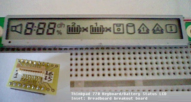
However this isn't just going to be about using the LCD driver, it's going to be about using an actual LCD from a commercial product that was used with this driver. This particular LCD is/was used in Thinkpads to show the battery, keyboard, hard drive and removable drive status. It features three 7-segment display digits, two battery level indicators, num lock, caps lock, scroll lock, speaker and two disk drive icons that can be individually controlled.
The LCD module has a 16-pin flexible connector that plugs into a connector on the mainboard. If the laptop is dead or scrap then the connector can be desoldered and attached to a 'normal' 16-pin surface mount breakout board, offset slightly to compensate for the pins being staggered.
The LCD controller controls all LCD segments except for the speaker, FDD and HDD icons. If those are wanted then they will have to be driven by an external signal like the output waveform of the LC75812 driver IC in static duty mode. Methods of generating that signal include hpwm in pwmhalf mode or normal PWM plus XOR gates controlled by the PICAXE to turn on each segment.
LCD Module Pinout
ADC/7-segment example
The LCD is driven in 1/2 duty mode, despite there being less than 53 segments. Writing the data to the LCD is simple - force CE high, output 56 bits containing display data with the final byte being $FC, then make CE low again. The /INH pin turns off the LCD when made low and turns it on when made high.
The following shows which bit represents each segment. D1 gets sent to the LCD first.
The 7-segment displays are the most useful items on this display so the example will use those. The shapes of the segments are not identical to those on a normal LED 7-segment display but are quite common for LCD and VFD displays. On these displays, I'd say that the 6 should have a 'tail' (segment a on), the 9 should not (segment d off) and for the number 7, it (segment f) doesn't matter.
PICAXE's weak mathematical capabilities make writing to the 7-segment displays a bit messy as each one has a different bit order however the 'bit' variables on PICAXE allow it to be clearly seen what is going on.
This example, which is designed for a PICAXE-20X2, reads the ADC level on pin C.2 and displays it on the 7-segment displays. Leading zero blanking is implemented. The code is not commented but it shouldn't be difficult to see what is going on.
The variables disp1-6 control what segments will be lit. The pause 100 is to prevent rapid changes in the display, not because the PICAXE must wait for the display to update before it can write again. The spislow setting can be changed according to PICAXE clock speed - even spifast works at the default clock speed of 8MHz. Timings for the driver IC are in the datasheet.
Controlling the speaker/FDD/HDD icons
An AC square wave must be used to drive these segments. One way of generating this is to use HPWM to control one icon if you just want one e.g. hpwm pwmdiv16,pwmhalf,pwmHHHH,0,255,511 will generate two complementary square waves.
Another method is to generate a single square wave and use XOR gates to select between normal and inverted waveforms for each icon's pin. The normal waveform will be connected to the common pin at all times.
However this isn't just going to be about using the LCD driver, it's going to be about using an actual LCD from a commercial product that was used with this driver. This particular LCD is/was used in Thinkpads to show the battery, keyboard, hard drive and removable drive status. It features three 7-segment display digits, two battery level indicators, num lock, caps lock, scroll lock, speaker and two disk drive icons that can be individually controlled.
The LCD module has a 16-pin flexible connector that plugs into a connector on the mainboard. If the laptop is dead or scrap then the connector can be desoldered and attached to a 'normal' 16-pin surface mount breakout board, offset slightly to compensate for the pins being staggered.
The LCD controller controls all LCD segments except for the speaker, FDD and HDD icons. If those are wanted then they will have to be driven by an external signal like the output waveform of the LC75812 driver IC in static duty mode. Methods of generating that signal include hpwm in pwmhalf mode or normal PWM plus XOR gates controlled by the PICAXE to turn on each segment.
LCD Module Pinout
| Pins | Function |
| 1 | Common for FDD/HDD/Speaker icons |
| 2 | FDD icon |
| 3 | HDD icon |
| 4 | Speaker icon |
| 5 | CLK |
| 6 | DATA |
| 7 | CE |
| 8 | /INH |
| 9-10 | VDD |
| 11-13 | N/C |
| 14-16 | VSS |
ADC/7-segment example
The LCD is driven in 1/2 duty mode, despite there being less than 53 segments. Writing the data to the LCD is simple - force CE high, output 56 bits containing display data with the final byte being $FC, then make CE low again. The /INH pin turns off the LCD when made low and turns it on when made high.
The following shows which bit represents each segment. D1 gets sent to the LCD first.
Code:
#remember that hspiout is MSB FIRST! (D1 = bit7...)

D1 - 7seg1 a - first bit
D2 - bat2 number
D3 - 7seg1 b
D4 - 7seg1 f
D5 - 7seg1 d
D6 - 7seg1 e
D7 - 7seg1 c
D8 - 7seg1 g

D9 - 7seg2 a
D10- 7seg colon
D11- 7seg2 d
D12- 7seg2 e
D13- 7seg2 c
D14- 7seg2 g
D15- 7seg2 b
D16- 7seg2 f

D17- 7seg3 d
D18- 7seg3 e
D19- 7seg3 c
D20- 7seg3 g
D21- 7seg3 b
D22- 7seg3 f
D23- unit %
D24- unit h

D25- 7seg3 a
D26- unit d
D27- bat2 seg1
D28- bat2 seg2
D29- bat2 surround
D30- bat2 arrowright
D31- bat2 arrowleft
D32- bat2 diamond

D33- bat2 seg4
D34- bat2 seg3
D35- bat1 seg1
D36- bat1 seg2
D37- bat1 surround
D38- bat1 arrowright
D39- bat1 arrowleft
D40- bat1 diamond

D41- bat1 seg4
D42- bat1 seg3
D43- numlock
D44- bat1 number
D45- capslock
D46- scrolllock
D47-
D48-

#endremPICAXE's weak mathematical capabilities make writing to the 7-segment displays a bit messy as each one has a different bit order however the 'bit' variables on PICAXE allow it to be clearly seen what is going on.
This example, which is designed for a PICAXE-20X2, reads the ADC level on pin C.2 and displays it on the 7-segment displays. Leading zero blanking is implemented. The code is not commented but it shouldn't be difficult to see what is going on.
Code:
symbol ce = B.6
symbol temp = b0
symbol disp1 = b1
symbol disp2 = b2
symbol disp3 = b3
symbol disp4 = b4
symbol disp5 = b5
symbol disp6 = b6
symbol dig1 = b7
symbol dig2 = b8
symbol dig3 = b9
symbol adcval = b10
table 0,($3f,$6,$5b,$4f,$66,$6d,$7d,$7,$7f,$67,$0)

main:
	hspisetup spimode00,spislow
	do
		readadc 8,adcval
		dig1 = adcval dig 2
		dig2 = adcval dig 1
		dig3 = adcval dig 0
		gosub display
		pause 100
	loop
	end

display:
	if dig1 = 0 then
		dig1 = 10
		if dig2 = 0 then
			dig2 = 10
		end if
	end if
	readtable dig1,temp
	bit15 = bit0
	bit13 = bit1
	bit12 = bit5
	bit11 = bit3
	bit10 = bit4
	bit9  = bit2
	bit8  = bit6
	readtable dig2,temp
	bit23 = bit0
	bit21 = bit3
	bit20 = bit4
	bit19 = bit2
	bit18 = bit6
	bit17 = bit1
	bit16 = bit5
	readtable dig3,temp
	bit31 = bit3
	bit30 = bit4
	bit29 = bit2
	bit28 = bit6
	bit27 = bit1
	bit26 = bit5
	disp4 = bit0 << 7
	high ce
	hspiout (disp1,disp2,disp3,disp4,disp5,disp6,$FC)
	low ce
returnControlling the speaker/FDD/HDD icons
An AC square wave must be used to drive these segments. One way of generating this is to use HPWM to control one icon if you just want one e.g. hpwm pwmdiv16,pwmhalf,pwmHHHH,0,255,511 will generate two complementary square waves.
Another method is to generate a single square wave and use XOR gates to select between normal and inverted waveforms for each icon's pin. The normal waveform will be connected to the common pin at all times.