Hello,
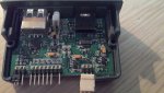
I'm currently working on a project using the Vinculum Vmusic2 module to play MP3 files to accompany a PICAXE controlled fountain display. I have recently finished building my circuit, and switched it on, only for the Vmusic2 to literally explode.
It was connected to a pair of 8R, 10W speakers (http://tinyurl.com/ll6zjlz), one on each line out, with a common ground, a 5V supply, regulated down from 12V, my 0V rail and an output from my 40X2. I believe I can discount a fault within the module, since I have tested it on its own, on a breadboard, and also a supply voltage above 5V, because my PICAXE and OLED, both 5V, still work perfectly. I also wasn't using the module at the time, there wasn't even a USB stick in it!
Does anyone have any ideas what might have caused this and how I can stop it happening to my replacement module?
Thanks in advance.