Hardware not found error

AndersK

New Member
Could need some help here

Have a PICAXE 14M starter pack but cannot connect to it.

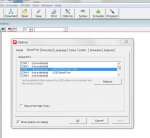
Using a AXE027 USB cable, checked the cable with the troubble shooter and it seems to be ok

Drivers downloaded and installed without errors (did it twice with uninstall between)

Power supply is 3x AA batteries, new

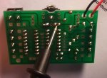
Measured voltage on chip, looks ok and correct polarity

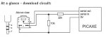
Checked paths between 3,5 mm connector to chip, nothing wrong there

Checked all resistors on the board and seems to be assembled correctly

Any ideas?
 

sonny

New Member
Wat os are u running i had same problem with my windows 7 64 bit

emails address removed

ill explain in detail how i fixed my problem
 
Last edited by a moderator:

AndersK

New Member
Running XP on this one

(emails exchanged) Will try and go over all com ports to see if one will work.

Every advice is appreciated
 

AndersK

New Member
Srnet, sorry I misunderstood your suggestion
Thought you meant whats under "Configure and test"

I cant find whats reffered to , or dont understand the instructions:
click on the menu options View -> Options. Select the Serial Port tab, tick Show Port Help Tools, then click the Test Port button.

Also tried 27 differnt COM ports today without success.


AndersK

New Member
Thanks, that made sense. Have never used version 5.

Tried it:
4) When the LED is off, the signal should be between 0V and -1V. OK -0,4V
5) When you click on the LED the signal should switch high. ? +3,8 V

Also sent an email to the support with some pics of the board attached
 

rq3

Senior Member
Thanks, that made sense. Have never used version 5.

Tried it:
4) When the LED is off, the signal should be between 0V and -1V. OK -0,4V
5) When you click on the LED the signal should switch high. ? +3,8 V

Also sent an email to the support with some pics of the board attached
If it's an actual LED, is it connected in the right direction? Does it have a forward voltage less than 3.8 volts? (many blue and white leds require more than 3.8 volts to turn on).

Rip
 

AndersK

New Member
inglewoodpete:258943 said:
The voltages appear to be correct. Your next step is to do a loopback test for data. Follow the steps outlined by Goeytex here.
That test passed too.

Found a 2V drop over two of the legs of the 3,5mm contact that are supposed to be connected internally and then to ground.
Will try and solder them together tonight.
 

AndersK

New Member
It's alive......:cool:

Connected the legs with solder and that did it.
Dont know why it caused a problem because the download circuit shows there is an internal connection between them and tech support said the board itself should connect them as well.
Anyhow, now the fun can begin :D

Thanks to all that engaged in helping me out.

DSC_0368_2.jpgdownload circuit.jpg
 

Technical

Technical Support
Staff member
Its most likely you accidentally damaged(broke) the track when soldering. But glad you got it going.
 
Top