Newbie needs help with 08m2+ schools experiment board

Ifixit

New Member
My picaxe supplier went under here in NZ who originally supplied me an 08m starter pack.

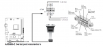
I built it and it was working. 2 years later built new PC using an Asus A55BM-E motherboard which had a serial port but no DB9 and cable. So pulling the serial port off an OLD pc i plugged it in and nothing, picaxe editor can't communicate with the picaxe board.

Thinking after time it might be broken I purchased an 08m2+ chip a pack of 330 ohm 1/4 watt and 22k 1/4 watt resistors which arrived today plugged em in still can't communicate with board using the picaxe editor software.

Have serial port 1 in Dev manager running vista x64 SP2.

Now my biggest issue is the "howto" that came with it originally is misplaced and i was sure to program it i had to connect a resistor somewhere i tried one from pin one to it opposite connector and tried pin 2 (R0A and R0B) still nothing. Down by JP1 (serial in plug) are some sil sockets labeled serial in/serial out 0v 5v and pin 0 am i supposed to connect a resistor there somewhere?

Could my serial cable type (db9 to MB) plug be wrong type as a pc engineer many years ago i remember there was a type 2 and type 6 cable?


some questions

What speed do i set the serial port too in Dev manager? 9600? fifo on off? Hardware control settings?

Where can i get info for the schools experiment board to show me how to set it up again as in NZ the supplier of the schools boards has disappeard and the boards here seem basic or quite different.

Where is the reset button?

At a loss any heads ups or advise would be appreciated.

PS the School experiment board i built is NOT AXE92 from surplustronics they have the board i built but no components or info it's called a pic patch 08 hope that helps you to help me if you can. I got that wrong but cannot correct the post.
 
Last edited:

Goeytex

Senior Member
The first thing you need to do is verify the PC serial port. Do a loop back test:

1. Connect the Picaxe serial download cable to the serial port (Do not plug the stereo connector into Picaxe Board)
2. Attach a paper clip to the stereo connector as shown below.
3. Open the Picaxe Programming editor. > Options > Serial Port. Select Com1 or the Port that is shown in device manager, Click OK
4. Press F8 to open the PE Terminal
5. Type something in the bottom window then click on send.​

If the port is working correctly what you typed will be echoed in the large receive buffer window.

If this test works then something else is amiss. Let us know how this test comes out.
 

Attachments

Ifixit

New Member
I got zilch reply something seems wrong with my serial port or the plug in DB9 232 too motherboard cable/plug i presume.

I didn't have a paper clip used a piece of solder instead.

tested serial cable( for the picaxe the one with the stereo plug thinks it's called the download cable). bottom row with 5 pins i get loop back sound from multimeter on 3 pins so seems the download cable is ok has to be type of serial to motherboard connector that the download cable plugs into is wrong type or faulty. Any guru's here know which type of cable is for Asus motherboards as i cannot for the life of me recall whether it's the type 2 or 6 and how to even tell them apart.
 
Last edited:

Goeytex

Senior Member
Attached is a graphic from the Asus A55BM-E Manual.

Of interest is the pinout of the board connector. Pin1 is RXD and Pin2 is TXD. You can connect these pins together at the mother board using a jumper wire with a 1K series resistor ( protection). And then do the loop back test again.

As far as the connector / cable type .... it should be pin for pin, where mother board COM Pin1 connects to DB9 Pin1, MB pin 2 to DB9 Pin 2 ... and so on. Maybe verify that you have the correct cable with an ohm meter.
 

Attachments

inglewoodpete

Senior Member
I'm waiting for delivery of a DE9 to motherboard header cable for a Gigibyte MB but that's not an ASUS, is it? ;)

The header for mine seems to be bare pins. Can it be accidentally reversed?

Do you get a voltage between pins 3 and 5 on the DE9 socket (measure with a multimeter)?
 

tarzan

Senior Member
Now my biggest issue is the "howto" that came with it originally is misplaced and i was sure to program it i had to connect a resistor somewhere i tried one from pin one to it opposite connector and tried pin 2 (R0A and R0B) still nothing. Down by JP1 (serial in plug) are some sil sockets labeled serial in/serial out 0v 5v and pin 0 am i supposed to connect a resistor there somewhere?


Where can i get info for the schools experiment board to show me how to set it up again as in NZ the supplier of the schools boards has disappeard and the boards here seem basic or quite different.
http://www.surplustronics.co.nz/product/PICPATCH/info-316.pdf?1377665145
 

Ifixit

New Member
Thank you all for the invaluable information. What an awesome forum.

Looking at that diagram my cable won't work with this serial port in it's current config. On the end of the download cable loopback (or continuity test) to the stereo plug using a multimeter shows 3 pins on the bottom row(or the row with 5 pins) connects yet i see in the brilliant image you supplied that one pin is in the 1st pin in the top row(4 pins). if i jumper it, i won't be able to use the motherboard serial plug as it won't fit in socket and i'm a little scared i'll short the Motherboard out. However after work today i'll try modifying the actual MB cable and see if i can get it to work with a little modification.

Thanks for the info on my Pic Patch board that's it! KEI i could not find anymore on the web but that is my exact model board thank heavens i found (err someone else), found it. Your all brilliant.

I wonder, am wondering, is there not a way to swap the pin outs software wise in vista? IE can i not redirect the outputs for the serial ports using software? Other than that i might head to TACS(PC guys in my city) see if they have the right riser plug for the MB.


EDIT

AHH reading your post "properly" Goeytex i'll try that loopback test in about 8 hours when i get back from work i see what you meant now. In the image you supplied on the right hand side with the plug you actually plug into the DB9 socket 3 pins on the top(5 pin row) do seem to be right and correct to my continuity test of the download cables pin out. I'll need to check the ports actually functioning using your method of looping back the pinouts for rxd and txd( rec and trans) and testing with the picaxe editor that should give me a definitive that the serial port functions or not then if so i can build up a cable. Failing that i may bite the bullet and just buy the USB download cable from surplustronics. Surely it's got to be easier than all this faffing about trying to get a proper motherboard riser cable which you would think the guys at Asus would supply with the new motherboard.

Cheers and a big thanks guys.
 
Last edited:

Ifixit

New Member
Jumpered the db9 male socket pins 2 and 3 zilch reply from picaxe editors F8 function.

Multimetered the cable is a straight through pins 1-9 go 1-9 think pin 10 was non connected which is about right.

From what i can find out there is an at-everex type of serial cable and a another which seems what asus use but swap pin 3 for pin 5.

Building cable from scratch only need three pins connected how hard can it be. Little common sense and just match pins on download cable to match the tx rx n gnd off the board using the diagram you provided Goeytex.

EDIT

Built cable from 2 serial cables spliced in the middle used multimeter and diagrams, soldered wires together tested and now loopback using the picaxe editor works! On to trying my picaxe unit.

Awesome guys couldn't have solved this without your valuable assistance or would have taken me twice as long provided i came up with the idea to start with.

Picaxe editor when i check the 08m2+ firmware ...your firmware is firmware 4A ....and A is for Awesome!!!!!!

It's alive!!!!!

Thanks, thanks, thanks ,and again thanks everyone.
 
Last edited:
Top