adding rechargable battery-backup to picaxe circuit

BooMod

New Member
I want to build a special LED clock as a gift, powered by mains through a 6V transformer and a 5V power regulator. I have over the past year worked on some prototypes and am confident that I can make the doing-part work just fine. Im running on about 4.9V all said and done in the prototypes.

However, the location where this clock will end up as home is on an old country circuit that frequently gets brownouts and transient blackouts long enough to clear the time settings, and require them to reset the clock each time.

I would like to consider grabbing some rechargable cells from my local electronic shops, in whatever form may be best - rechargable phone packs, individual cells ... 1.2V x 4 NiMH or NiCad... and integrating them into the circuit so that they act as a battery backup for a few minutes (usually will only need to buffer a few seconds to 30 seconds).

If it was just brownouts, i'd figure a few big capacitors would do the trick, but dont know exactly how big/many for ie 20 seconds of runtime, but i do want it to ride out most of the outages that will be on the scale of a minute.

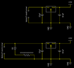
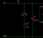
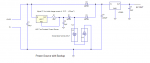
How do I add rechargable batteries into the circuit such that they recharge safely, but when the mains power is lost, the battery power then feeds the circuit. V1in is my 6V wall transformer, V1out is my ~5V regulator output, used to then power the main circuit. I know that they need some sort of charging circuit to control them and read in some places its a microprocessor controlled charging circuit, but not sure how, and how to integrate their power as a source when V1in drops to 0V

I have choices of 1A and 0.5A regulators, my circuit doesn't draw that much. I have wall transformers at 6V that deliver 0.6A and 1.0A that i can use (and i can find others if needed) in case big amps are needed for charging circuits..

V1in (6V) ===== [REGULATOR] ===== V1out (5V)
GND ============*============GND

I have a library of picaxe chips, lots of 08, 08M, 18X, 20X, 28X and 28X2s and a few others to call on. If i need to make a separate charging circuit with microcontroller feedback, i'd prefer it that way rather than tying it into the main circuit chip, because if I get a good solution, i'll likely include a rechargable battery backup module in several projects, and can just build that as a separate black box.

Some pointing into the right direction to make sense of what is needed, an implimentable solution is very much appreciated.
 

Hemi345

Senior Member
Are you using an RTC module in your design? On a project I did that used a DS1337, I used a coin cell battery and two blocking diodes on the V+ line on the RTC so the current from the coin cell wouldn't try to power the rest of the components when the main power failed and also so the coin cell wouldn't be 'charged' while the main power was active. Maybe the RTC you're using has a backup battery input already .

Another option is to get a 5.5V supercap and add it to your project just like a bulk cap. It'll charge up to your 4.9V supply and then power the system while the main power is out. No need to worry about any charging circuit, just put a current limiting resistor between it and your 5V regulator (like 20ohm) to protect the reg when the supercap is completely flat.

Maxim Integrated has a good calculator for figuring out how long something will run on Supercaps.
 

lbenson

Senior Member
>Another option is to get a 5.5V supercap

Roughly how many Farads? Digikey shows 9 pages of 5.5V supercaps.
 

hippy

Technical Support
Staff member
Roughly how many Farads?
That would probably depend on how much current it has to supply and for how long.

It wasn't clear what adding battery backup was meant to achieve beyond not losing settings; does it need to keep the PICAXE running and the LED display active through brownouts and surges, or is it acceptable for things to stop working as long as the time is correct when the supply recovers ?

If it's just to save resetting the clock after a glitch then I would have thought an RTC with coin cell battery backup alone would achieve that, no need for anything else.

If it's a self-counting system without an RTC so needs to keep going through power outages and glitches, then backup batteries would be required, and also if the display needs to always remain active. But if not worried about loss of display for a few seconds to minutes then switching to an RTC and coin cell battery would seem the easiest solution.
 

BooMod

New Member
Assuming the power regulator module with a the mains-transformer 6VDC output looks like the smaller upper in this picture, based on your schematic in that other post, I would guess it would just be the batteries and a resistor attached to the input power/gnd lines prior to feeding the regulator? Would it be on the scale of 1Mohm? Or would the batteries be 4.5V on the output line instead, and if so, resistor? Diodes required anywhere?

HEMI: How would a supercap be actually wired in as a replacement to the batteries idea, and how would the capacity need of it be determined if one knows how much millamps are being drawn by the rest of the circuit?

Power1.png
 

BooMod

New Member
For my application, I was just thinking simple with "switch over to rechargable batteries" and keep running the chip and LEDs on the alternate fuel source as long as possible, rather than worry about trying to come up with an "oh nos, mains went out, just keep running the picaxe program, but actually disable the LEDs until it returns!" circuitry /logic. Which is why I personally still would like a battery / rechargable battery based solution for the simplicity of the downstream-of-power-sourceline issues
 

lbenson

Senior Member
So what do you expect your current draw to be?

In the circuit diagram in the thread I posted note the two BAT85 diodes, D1 and D2, which are needed to keep one source from interfering with the other--that would be the same whether the batteries are rechargeable or not.

For recharging, posts have indicated that .1C is appropriate for maintenance charging of NiCads. There are a fair number of related threads, but I don't have links available.
 

Hemi345

Senior Member
Yep, srnet's link is the one I mentioned. The calculator is pretty close to what I'm getting in my project. I got a few supercaps to play with; a couple Maxwell 2.7V 5F and a Cooper 5.5V 1.5F. With a current draw of about 6mA, it was able to power the project (without disabling of brown out detection or anything) on two of the 5F supercaps in a series (so 2.5F) for about 12 minutes starting at 4V (didn't wait till the supercaps were fully charged) till the PICAXE shutdown at 1.9V. Since all the components in my project will operate on as little as 1.9V, I switched to just one of the 2.7V supercaps and got about 10 minutes starting with the cap charged to 2.5V till the PICAXE quit logging the voltage at 1.9V. I haven't had a chance to play with the 5.5V cap but I believe it would make a good backup if main power outages usually only last for a few minutes. And they can be charged 100s of 1000s of times as long as you don't exceed their maximum voltage rating (can't put a single 2.7V rated supercap on your 4.9V rail).

Just depends on what your project's current draw is if it makes sense to use supercap.
 

Attachments

john2051

New Member
Hi, it looks like you missed out the bridge rectifier from your first circuit, and bulk smoothing.
I would stick to the simplest method, and if its a clock chip, they last a fair while on a coin cell.
You can even get a lipo coin cell that can be re-charged!
regards john
 

BooMod

New Member
Ah I just realized that RTC = realtime clock I was kinda scratchign my head thinking it was referring to a particular resistor-capacitor circuit...

I'm not planning to use a real-time clock system... My system will use just a self-incrementing system to advance the indicators, but i've found the picaxe does a great job of ticking time without losing/gaining huge amounts compared to some of the other oscillating-timer designs i have tried. Plus I can use the inputs on the picaxe to speed-up the setting of the hour and minutes by short-cutting the process, and even adding a reverse-time feature to fine tune the time, rather than around-we-go-again.. not 100% sure on that yet.

So again, for me it comes down to integrating batteries or rechargable batteries to replace the sudden loss of input from the 6V wallwart, to keep things on the status-quo. And again, an integration method that is independant of being tied to a clock-chip means reusability of the method for other things.

If I understand the one design correctly, I need a diode on the Vline from the 6V feeding into the common-voltage line for the regulator, to isolate the batteries/backup batteries from bleeding out to the wallwart when that source stops. Is a diode required in line with the battery pack as well? What type of diode would be required for 6V->common voltage input, clearly not a teeny signal diode, but what ..'size' for lack of the word I can't think of right now...
 

lbenson

Senior Member
Picaxe itself doesn't draw much current. Depending on what you do draw, the nominal 150mA from a teeny 1n4148 signal diode might be plenty.

Yes, diode in line from the battery pack as well--but for charging, you have to have some way of getting the charging current to the batteries. Have you found a circuit yet?
 

Hemi345

Senior Member
I think I'd use lbenson's low power design with blocking diodes and plain alkaline batteries. Unless the mains power is that aweful, those batteries should last a really long time.
 

Goeytex

Senior Member
Here is a simple design I did that uses an LM317 as a constant current source to trickle charge 2 cheap NiMh batteries. Do not use LiIon batteries as they should not be trickle charged. The charge rate should be .03 * C . So if the batteries are rated at 800 maH that would be about 24ma. I think that anywhere from 10 to 20ma should keep them topped off OK. 10ma is about the minimum that the LM317 can regulate as a constant current source.

This circuit requires a 12 DC supply because the LM317 is not an LDO and has significant overhead. A switching type 12V DC Wall Wart will be fine. The 5v regulator needs to be an LDO because the batteries will supply less than 7v after the diode drop. Do not use an LM7805. The LP2950 works very well and can supply up to 100ma. If the 5v circuitry needs more than 100ma then a different LDO needs to be selected. I would suggest a Microchip MCP1702, good for up to 250ma.

The charge rate is adjusted via R1 so make R1 a 200 ohm Pot and with freshly charged batteries adjust until the current is .03 * Battery capacity. This should be around 20 - 25ma depending upon the battery rating.

I used a 2200uf bulk capacitor (C3) since I have a drawer full of them, but anything above about 220uf should be fine.

The transition from the 12v Supply to batteries is seamless and glitchless.

The schematic shows 2 cells, but 6 will be needed for 7.2volts. If the Picaxe circuitry operated at 3.3v instead of 5v the number of batteries could be reduced.
Good Luck
 

Attachments

Last edited:

nekomatic

Member
Do you find that circuit successfully recharges the NiMH cells after they've been significantly discharged by a period without mains power, or does it only maintain them at full charge after they've previously been charged up in a 'proper' charger?
 
Top