WHITEKNUCKLES
New Member
Over the past year I have invested some time and very little money in a new hobby, collecting 'essential' electronic items from China via ebay at the absolute minimum auction prices.
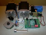
One of these was a TB6560 driver board identical to the one in the first link but at a somewhat lower price.
Using a surprisingly cheap laptop power supply rated at 19v and 3.2A I ran a number of bipolar steppers using an 08M Picaxe.
S: Pulsout 1,5: pause 1: goto s
The smallest motor is a surplus head positioning threaded rod motor.
15mm diameter 10.5mm long 15g 14 Ohms. Runs well at 0.3A.
Next is courtesy of Stan Swan who showed that they can be driven directly from Picaxe output pins. Thanks again Stan.
20mm diameter 14mm long 20g 115 Ohms. Runs well at 0.3A.
One of a collection of rescued printer steppers.
42mm diameter 15.5mm long 94g 12 Ohms. Runs well on 0.3A and 0.5A.
Hybrid from Arceurotrade.
57 X 57 X 76mm long 1.1Kg 4 Ohms 4.5v 2.5A/Phase 180N.cm. Runs well from 0.3A to 2A.
Hybrid from CNC4YOU.
60 X 60 X 88mm long 1.4Kg 2.6 Ohms 5.46v 2.1A/Phase 3.1N.m. Runs well from 0.5A to 2A.
Functionality is well illustrated in the first link, the second is for a UK seller with a link to a forum and a clear picture of possible connections.
I would point out that I use only the step input and a return to the Picaxe as the reverse and enable functions need only be connected when required.
Opto isolators on these functions mean that there need be no common ground connection between the Picaxe and the driver board.
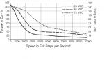
There are 14 possible settings for the regulation of phase current from 0.3A to 3A irrespective of the nominal voltage and resistance of the motor. The inductance of the motor windings delay the build up of the current in the windings but the higher supply voltage can overcome this to some extent up to the point where current regulation circuit holds the current 'effectively' steady for the length of the motor step.
Microstepping at 2, 8 and 16 works well on all these motors and there is some evidence on the web that very high rates can be contraputical.
When powered and stationary between steps the motor presents only the resistance of the coils so the board cuts the current to a choice of 50% or 20% of the selected value. The faster a motor steps the less current it can draw allowing small motors to be powered at the 300mA setting with only 60mA while stationary.
All the motors run normally at different Decay settings, subjectively I sense that there is increased smoothness at the highest settings on the bigger motors but feel that testing would be needed for best results.
These boards have not had a good response on the web and granted the Datasheet states that the 5v to the logic circuit must be connected before power is applied to the motor. An onboard regulator supplies the logic, however the 10V to 24V specification for these boards is lower than the 40V VM A/B on the Datasheet.
Dave
http://www.ebay.co.uk/itm/TB6560-3A-Driver-Board-CNC-Router-Single-1-Axis-Controller-Stepper-Motor-Drivers-/350922320630?pt=UK_BOI_Industrial_Automation_Control_ET&hash=item51b499aaf6
http://www.ebay.co.uk/itm/TB6560-3A-Single-axis-Stepper-Motor-Driver-Controller-Board-/141106624015?pt=UK_BOI_Electrical_Components_Supplies_ET&hash=item20da9c360f
One of these was a TB6560 driver board identical to the one in the first link but at a somewhat lower price.
Using a surprisingly cheap laptop power supply rated at 19v and 3.2A I ran a number of bipolar steppers using an 08M Picaxe.
S: Pulsout 1,5: pause 1: goto s
The smallest motor is a surplus head positioning threaded rod motor.
15mm diameter 10.5mm long 15g 14 Ohms. Runs well at 0.3A.
Next is courtesy of Stan Swan who showed that they can be driven directly from Picaxe output pins. Thanks again Stan.
20mm diameter 14mm long 20g 115 Ohms. Runs well at 0.3A.
One of a collection of rescued printer steppers.
42mm diameter 15.5mm long 94g 12 Ohms. Runs well on 0.3A and 0.5A.
Hybrid from Arceurotrade.
57 X 57 X 76mm long 1.1Kg 4 Ohms 4.5v 2.5A/Phase 180N.cm. Runs well from 0.3A to 2A.
Hybrid from CNC4YOU.
60 X 60 X 88mm long 1.4Kg 2.6 Ohms 5.46v 2.1A/Phase 3.1N.m. Runs well from 0.5A to 2A.
Functionality is well illustrated in the first link, the second is for a UK seller with a link to a forum and a clear picture of possible connections.
I would point out that I use only the step input and a return to the Picaxe as the reverse and enable functions need only be connected when required.
Opto isolators on these functions mean that there need be no common ground connection between the Picaxe and the driver board.
There are 14 possible settings for the regulation of phase current from 0.3A to 3A irrespective of the nominal voltage and resistance of the motor. The inductance of the motor windings delay the build up of the current in the windings but the higher supply voltage can overcome this to some extent up to the point where current regulation circuit holds the current 'effectively' steady for the length of the motor step.
Microstepping at 2, 8 and 16 works well on all these motors and there is some evidence on the web that very high rates can be contraputical.
When powered and stationary between steps the motor presents only the resistance of the coils so the board cuts the current to a choice of 50% or 20% of the selected value. The faster a motor steps the less current it can draw allowing small motors to be powered at the 300mA setting with only 60mA while stationary.
All the motors run normally at different Decay settings, subjectively I sense that there is increased smoothness at the highest settings on the bigger motors but feel that testing would be needed for best results.
These boards have not had a good response on the web and granted the Datasheet states that the 5v to the logic circuit must be connected before power is applied to the motor. An onboard regulator supplies the logic, however the 10V to 24V specification for these boards is lower than the 40V VM A/B on the Datasheet.
Dave
http://www.ebay.co.uk/itm/TB6560-3A-Driver-Board-CNC-Router-Single-1-Axis-Controller-Stepper-Motor-Drivers-/350922320630?pt=UK_BOI_Industrial_Automation_Control_ET&hash=item51b499aaf6
http://www.ebay.co.uk/itm/TB6560-3A-Single-axis-Stepper-Motor-Driver-Controller-Board-/141106624015?pt=UK_BOI_Electrical_Components_Supplies_ET&hash=item20da9c360f
Attachments
-
 841.3 KB Views: 59
Last edited: