Nokia 3310 GSM Autodialer

the old fart

Senior Member
Hi Guys,

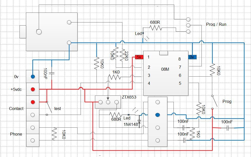
Looking at the circuit,

What would you think the Pic program is?

It's not a pin for pin for an 08 chip.

connection to the mobile is via the headset lead, so no modification of the phone keyboard.

My guess is a timer, but the resistors/capacitors are a mystery.

I already have the Nokia 3310 and the lead, I don't chuck anything out......

Will post the results as a working project when sorted.


Code:
http://www.youtube.com/watch?v=NAFwIyFfMgY#t=62


TOF
 

the old fart

Senior Member
Some progress on this.

the reed relay wakes the phone up, then switches off.

the IC then sends an audio command/noise which the phone matches to its own saved audio commands.

I programmed the phone with tune piezo,4,($70,$60,$50,$60,$70)

when I play back the tune, the phone dials out the preset number.

Should be easy enough to program an '08' to simulate this.

TOF
 

vttom

Senior Member
I thought maybe it was sending DTMF touch tones. Using the phone's "voice tag" feature is very cleaver indeed. Seems extremely doable with PICAXE.
 

the old fart

Senior Member
working code.

Code:
#picaxe 08m2

start:
high c.0

if pinc.3=1 then gosub dialout1


goto start

dialout1:
low c.0
high c.4
pause 3000
low c.4

pause 1000

tune c.1, 4,($30,$40,$50,$40,$50,$60,$70)

pause 4000


for b2=1 to 50
tune c.1,3,($50,$40,$30,$20)
next b2


pause 2000


return
program the phone via the circuit, ie trip alarm when phone says speak now to set setup voice command.

c.0 led in standby
c.1 play tune
c.3 switch input, + 10k0 resistor to 0v
c.4 to relay, via transistor and led
else circuit as above

3310 phone, pins 2&4 on jack pug
3109c phone, pins 3&4 on jack plug.


2.5mm 4pin plug

pin is 1
outer ring is 2
inner ring is 3
sleeve is 4
 

hippy

Ex-Staff (retired)
Finished Circuit
It's not clear how the 10K in the download circuit is connected but seems to be connected to the wrong end of the 22K.

The LED for the PROG/RUN selector has no current limiting resistor. You could probably do away with the selector and have a LED+R across Serial Out to 0V.

The LED on the ZTX653 also seems to be missing a current limiting resistor.

Decoubling capacitors would also be advisable.
 

the old fart

Senior Member
Led's I use don't have resistors, good for 3-24vdc.

that 10k should have gone to 0v.

Was wondering if transistor is needed, will put a resistor in.

Is the transistor even needed, 10 mA reed relay coil, 12.5mA total with Led.
 
Last edited:
Top