Pin-protected Web-enabled 28X2 Home Security System

lbenson

Senior Member
Since this thread is about a security system, I’ll start with a disclaimer:

Use or modify the accompanying code as you wish. It is not guaranteed or warranteed to be suitable for the protection of persons or property.
USE AT YOUR OWN RISK!


This is another version of the picaxe web server that I wrote about here (see that thread for more details about the “table-driven” program): http://www.picaxeforum.co.uk/showthread.php?25050-Picaxe-Web-Server-Water-System-Monitor-and-Controller

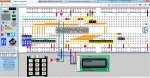
This picaxe web server models the monitoring of 10 sensors—8 windows and 2 doors, with the windows configured as zone 1 and the doors as zone 2. The outline of the building is roughly shown in ASCII art, and the condition of the sensors is shown with colored indicators.

The system could use standard open/closed sensors, which are ordinarily “normally closed”. Instead it implements a version of “Fully Supervised Loop” (“FSL”) monitoring, with resistors in the control panel and in the sensor which allow different conditions to be detected with ADC.

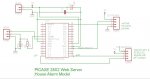
Various FSL implementations are possible. This uses 4 resistors with “normally open” sensors to detect 5 conditions, of which 3 represent wiring faults or tampering. The conditions are—Line to sensor cut, positive line to sensor externally grounded, lines to sensor shorted, sensor closed (e.g., window open) and sensor open (window closed). The resistors used are subject to modification, but I used the following


With a 5 volt power supply to the picaxe, the resistors shown will give the following nominal voltages and ADC readings:
Code:
Line(s) to sensor cut:              5V, 255
Normal sensor-open position:      4.2V, 218
Normal sensor-closed position:    2.7V, 138
Sensor lines shorted:             0.7V,  39
Positive line to sensor grounded:   0V,   0
The color coding on the web page is as follows: Black=positive sensor line shorted to external ground; Grey=lines to sensor shorted; purple=lines to sensor cut; Red=window/dooropen (sensor closed) when alarm is armed; Green=window/door closed (sensor open) when alarm is armed ; Orange=window/door open (sensor closed) when alarm is disarmed); Lime=window/door closed (sensor open) when alarm is disarmed.

The system, as configured, has 4 display states—alarm off, zone 1 armed, zone2 armed, and zones 1 and 2 armed. The image shown above is disarmed (alarm off), with open doors/windows showing orange, and closed showing lime.

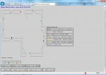
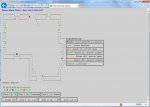
The first attached image shows both zones armed, with the open doors/windows changing to red, and closed changing to green. The second attached image shows only zone 2 armed, with the correctly wired windows showing lime and the doors (Zone 2) showing red and green.

Note that security is a relative term when one is talking about a web-enabled device. This application uses a "pin" to keep the web page form name from being too easily guessed, but any security provided by the “pin” used in this application could easily be compromised if your network were compromised, or if your wifi was insecure, allowing snoopers to eavesdrop. On the other hand, many companies are starting to market web-enabled home security systems. Most employ more powerful devices which are better able to provide security than the picaxe--but how well is it implemented?
 

Attachments

Last edited:

lbenson

Senior Member
Schematic and Breadboard

Aside from the wiring for the sensors, the layout of the circuit is very straightforward. The only components are the 28X2, the I2C module which contains the RTC and 4K eeprom, and the header for the TCP serial in and out.

Here is the ASCII art layout. The schematic and pebble breadboard images are attached.
Code:
                 *Reset  1 |             | 28 B7 tcpout
                     A0  2 | A0          | 27 B6 Internal Alarm
                     A1  3 | A1      A13 | 26 B5 
                     A2  4 | A2      A11 | 25 B4
                     A3  5 | A3       A9 | 24 B3
                  SERIN  6 |    28X2  A8 | 23 B2
              SEROUT A4  7 |    I/O  A10 | 22 B1 
                     0V  8 |         A12 | 21 B0 
                     NC  9 |             | 20 +V 
                     NC 10 |             | 19 0V 
        Security Pin C0 11 |        HsIn | 18 C7 tcpin
      External Alarm C1 12 |         A18 | 17 C6
             LCD out C2 13 | A14     A17 | 16 C5 Keypad in
                 slc C3 14 | A4      A16 | 15 C4 sda

Port1:  Port2:

         5V |      | 5V
         0V |      | 0V
var15 W1 A1 |    A | C6
var14 W2 A0 |    A | C5 x
var12 W3 A2 |    A | C2 x
var11 W4 B4 |      | C1 x
var12 W5 B3 |      | C0 x
 var9 W6 B2 |      | A4
 var7 W7 B1 |    A | A3 BDoor var8
 var6 W8 B0 |    A | B5 FDoor var13
The “ports” show connections to the sensors.
 

Attachments

lbenson

Senior Member
Web Page

Here is the web page html template, with the variables indicated by the “~” preceding two digits.
Code:
<html>
<title>Home Security System</title>
<head>
</head>
<BODY bgcolor="#d0d0d0">
<form name='f1' method='get' action='A~03'><p>
<P style="margin-top: .01; margin-bottom: .01"><b><font color="blue"><font size="4">
House Alarm Status</font> -- Date: ~01 ~02<br>
</font></P>

<font size="2" color="black">
<font size="1" face="Courier New" color="Black"><br>
<table><tr><td><table><tr><td>~05
|---------|   |-------|     |--------|~14  |--------|<br>
|         |---|       |~13    |        |---|        |<br>
| |-------|~12  |-------|     |--------|   |------| |<br>
| |                          \                  | |<br>
| |                           \                 | |<br>
---                            \                ---<br>
 |~11                                              | <br>
 |                                              ~15| <br>
---                                             ---<br>
| |                                             | |<br>
| |                                             | |<br>
| |                                             | |---<br>
---                                             |    |<br>
 |~10                                             |--- |<br>
 |                                                 | |<br>
---                                                ---<br>
| |                                                 |<br>
| |                                                ~06| <br>
| |-------| ~09 |----------|                         ---<br>
|         |---|          |                          |<br>
|---------|   |--------| |                         ~07|<br>
                       | |                         ---<br>
                       | |                         / /<br>
                       | |                        / /<br>
                       | |                       / /<br>
                       | |\                     / /<br>
                       | | \                    | |<br>
                       | |  \                   | |<br>
                       | |---|    ~08|------------| |<br>
                       |     |     |              |<br>
                       |-----|     |--------------|<br>
Sensor Status:<br><TABLE><font size="2"><tr>
<td>01</td><td>02</td><td>03</td><td>04</td><td>05</td>
<td>06</td><td>07</td><td>08</td><td>09</td><td>10</td></tr><tr>
<td> ~06</td><td> ~07</td><td> ~08</td><td> ~09</td><td> ~10</td>
<td> ~11</td><td> ~12</td><td> ~13</td><td> ~14</td><td> ~15</td> 
~05</font></tr></TABLE>
</td></tr></table></td>
<td><table><tr><td><font size="3">
<b>Signification:<br>
<TABLE BORDER='1' CELLSPACING='0' CELLPADDING='5'><font size="2">
<TR><TD><font color="Black"><b>Black:</font></b> +line shorted to ground</td></tr>
<TR><TD><font color="Grey">Grey:</font> lines shorted</td></tr>
<TR><TD><font color="Red">Red:</font> Alarm on, switch open</td></tr>
<tr><td><font color="Green">Green:</font> Alarm on, switch closed</td></tr>
<tr><td><font color="Orange">Orange:</font> Alarm off, switch open</td></tr>
<tr><td><font color="Lime">Lime:</font> Alarm off, switch closed></td></tr>
<TR><TD><font color="Purple">Purple:</font> lines cut</td></tr>
</tr></table><br>
</td></tr></table>
</td></tr></table>
<TABLE BORDER='1' CELLSPACING='0' CELLPADDING='5'>
<TR><TD>Alarm is: ~16</TD>
<TD>Zone 1 is: ~17</TD>
<TD>Zone 2 is: ~18</TD></TR></TABLE> <br>
<TABLE BORDER='1' CELLSPACING='0' CELLPADDING='5'>
<TR><TD><input name='X' type='radio' value='0' onClick='this.form.submit()'>Alarm off</TD>
<TD><input name='X' type='radio' value='1' onClick='this.form.submit()'>Zone 1 on, 2 off</TD>
<TD><input name='X' type='radio' value='2' onClick='this.form.submit()'>Zone 2 on, 1 off</TD>
<TD><input name='X' type='radio' value='3' onClick='this.form.submit()'>Zone 1,2 on</TD>
</TR>
</TABLE>
</BODY>
</html>
There are 18 variables in all, 10 of them for the doors and windows (“~06”-“~15”), two for the date and time, one to help provide security (“~03”), one to enable fixed-font spacing in the web page (“~05”), and three to indicate the armed/disarmed status of the system and the two zones (“~16”-“~18”). Variable “~04” is unused.
 

lbenson

Senior Member
Eeprom Layout for Table-driven Code

As in the previous thread, the variables are defined in an excel spread sheet, and code for eeprom definitions is generated by an excel VBA program.
Code:
                                                         Default       Var
    var #     Data Item      Type  Source Address  Length  Value       Name         Description
        0 None                                 98       1
        1 Date                  5       0      99      13        vDate            mmm dd, yyyy
        2 Time                  6       0     112       6        vTime            hh:mm
        3 Session Code          9      28     118       5      0 vSession
        4 None                  0       0     123       0      0                  1st var register above b27
        5 Shift in/out &nbsp   10       0     123       0      0                  Shift in and out of replacing " " with "&nbsp"
        6 Sensor1              11      12     123       2      0 vWin1            FSL 8-bit analog source = pin
        7 Sensor2              11      10     125       2      0 vWin2            FSL ("0"-"3"--cut:open:closed:shorted)
        8 Sensor3              11       3     127       2      0 vBkDoor          FSL Back Door--Zone 2
        9 Sensor4              11       8     129       2      0 vWin3            FSL
       10 Sensor5              11       9     131       2      0 vWin4            FSL
       11 Sensor6              11      11     133       2      0 vWin5            FSL
       12 Sensor7              11       2     135       2      0 vWin6            FSL
       13 Sensor8              11      13     137       2      0 vFDoor           FSL Front Door--Zone 2
       14 Sensor9              11       0     139       2      0 vWin7            FSL
       15 Sensor10             11       1     141       2      0 vWin8            FSL
       16 Alarm on/off          1      10     143       2      0 vAlarmStat       ON/OFF
       17 Zone 1 Status         1      11     145       2      0 vZone1Stat       Armed/Disarmed
       18 Zone 2 Status         1      12     147       2      0 vZone2Stat       Armed/Disarmed
There are three new variable types, 9, 10, and 11. 9 is for a session code which is used to increase the security of the system. If you press the button attached to pin C.0 and enter a html request for page &#8220;Annnn&#8221;, e.g., http://192.168.1.65:8165/A1234, the system will record &#8220;1234&#8221; as your &#8220;pin&#8221; number (so you should choose a better number), and will from that number generate a session code which will be used to provide more security. Since the program otherwise uses only single-character form names, (e.g., &#8220;A&#8221;, &#8220;B&#8221;, &#8220;C&#8221;), this prevents someone from gaining access by entering the request without the pin.

Variable type 10 is a toggle, a &#8220;shift-in&#8221; / &#8220;shift-out&#8221; of substituting &#8220;&nbsp&#8221; for each instance of a space (&#8220; &#8220;). Since browsers condense multiple white-space characters to a single space, this is needed to make the ASCII art house plan maintain its form.

Variable type 11 is for the FSL analog read inputs. For them, the varSource is the ADC channel. Here is the full current specification of the 4-byte variable records:
Code:
Byte
0   data type
    0          no data item
    1          bit data--stored len 2 bytes, null terminated
    2          byte data--stored len 4 bytes, null terminated
    3          word data--stored len 6 bytes, null terminated
    4          temperature--stored len 5 bytes, null terminated
    5          date--store length from source field, which gives format
    6          time--store length from source field, which gives format
    7          text--variable
    8          chart
    9          Session Code--special variable generated from pin 
               for more secure web page
   10          shift-in, shift-out of replacement of " " with 
               &nbsp for fixed-font formatting
   11          Security System FSL (Fully Supervised Loop) analog
               readings to give 0,1,2,3: short,open,closed,cut
               for 5V,4K7,ADC,1K2,(6K8),0V->0,1V85,3V98,5V.
               Takes ADC channel as varSource
    %10nnnnnn  string data of up to 64 bytes (as designated by nnnnnn), null

1   source--variable holding data
    0          Special handling required or bit0 for bit data, or rtc for date/time
    0-31       bit variable number, e.g., bit13; type 11=analog8
                       or
    %10000000-%10011111 pin # 0-31 for digital input pin
    %11000000-%11011111 channel # 0-31 for analog 8-bit
    %11100000-%11111111 channel # 0-31 for analog 10-bit
               (Note for 20X2 extender, c.0-7=16-23; b.0-3=24-27)

    0-27       byte variable number, e.g., b24
    28-75      byte variable in ram accessed with peek/poke
    32-75      bit variable in ram accessed with peek/poke
    0-13       Word variable number, e.g., w5
    14-29      word variable in ram accessed with peek/poke

               RTC Date/Time
    0          Date: format mmm dd, yyyy, e.g., Nov 08, 2013
    0          Time: format hh:mm, e.g., 10:01--24 hour
    1          Date: format yymmdd, e.g., 131108
    1          Time: format hhmmss, e.g., 100133

    0          String: Normal text display
    1          String: Warning--displayed in red and emailed every 6 hours
    
2-3 address in ram of data string for output to html page
    except for bit variable, address in table of text for 0 values,
      address in table for text for 1 value
 
Last edited:

lbenson

Senior Member
The Code

The whole code for this project fits (barely) into slot 0 on the 28X2, using 4036 out of 4096 bytes available. The include file is 317 lines long, and the program 1295 (although many lines were for debugging and are commented out).

As in the previous web page picaxe program, there are 6 main parts to the code.

1) Definition of variables and setup of eeprom and table data. The include file defines the input ports, the named variables, named locations in RAM, other constants, and sets up the values for eeprom and table data. It includes the definitions generated by the excel macro.

2) initialization. This part of the code gets the date and time, updates values from the sensors, calculates the length of the html output, and performs other miscellaneous initializations.

3) Collection of input from the sensors (subroutine setOutputs). This routine loops through all of the web page variables using the eeprom table, reads the sensors, updates binary values which drive the web display, and sets the outputs as appropriate. This is code which is specific to an application, and would have to be rewritten for any specific purpose.

4) Building of text representation of the values to be displayed (subroutine updateData). This is the main &#8220;table-driven&#8221; part of the code. It loops through the variables defined in the picaxe eeprom, and and for each sensor, reads the analog value 10 times and averages it. It then determines which of 5 categories the value falls in&#8212;3 wiring faults and sensor open/closed.

5) Monitoring of HTTP GET requests (main loop of program). This is fairly simple. Background serial receive is set up, and when an html request arrives, the program calls the routine, parseInput to break out the form and security session code, and any data item/value pairs (at present, 4 pairs are parsed).

Only one pair is used in this application&#8212;for the 4 radio buttons which determine whether the system is armed&#8212;which could result in an alarm going off&#8212;or disarmed, and which of the zones is armed.

6 ) Output of the html code(subroutine outputHTML). This routine scans character by character through the html template. If it finds a variable (indicated by &#8220;~##"), it looks up the variable information in the eeprom table, and outputs the ascii data built by the last update (no more than a few seconds earlier) or outputs ascii characters from table memory, or calculates the proper language and byte image for each sensor; otherwise it outputs the character. This continues until a binary 0 is found. At 16mHz it takes up to 10 seconds for the output to be generated&#8212;nearly 10,000 characters. You can watch the page being built in your browser.
 

Attachments

Last edited:

lbenson

Senior Member
Network Connection, Additional Features, Conclusion

Network Connection

In the previous picaxe browser application, I used the TLG10UA03 Embedded Uart-Wifi module. In this one, I wanted a fixed lan connection. I used a router I had which was running openWrt, an ancient wl-500gPv2.

On this I ran ser2net, a program which provides communications between the network and a serial device. Ser2net has the advantage of enabling you to monitor either the tcp input (from the net) or the “terminal” output (from the picaxe). This helped with the debugging.

In the future I hope to set up a simpler and less expensive connection (although usb routers like the HAME A5 can be had for as little as $15US).

Additional Features

This system shows only on/off sensors enhanced with resistors so that various fault or tampering conditions can be detected. It would be relatively easy to add PIRs or breaking glass detectors, or other security sensors, as well as water intrusion or temperature sensors.

I put an LCD and keyboard on the pebble layout, but have not yet implemented them.

Conclusion

The picaxe is quite capable of monitoring sensors for a home security system, and providing a way to control it over the web. With a 40X2, you could monitor 24 analog FSL lines, and other sensors as well. With the web view, you can see at a glance which sensor was activated, and you can always tell immediately if there is a wiring fault.
 

lbenson

Senior Member
Additional Notes

Color Images
The byte-sized color images are 8 pixels wide by 12 pixels high png images which have been uploaded to tinypic.com. You can create different colors by downloading the white image, http://i41.tinypic.com/30cbqme.png, loading it into Microsoft Paint, and spraying it with the color of your choice. Then save it with a new name and upload it back to tinypic.com.


Pin Number
The pin number works like this. If you depress the pushbutton attached to C.2 and use your browser to enter an html request with a letter followed by a 4-digit number, e.g., 192.168.1.65:8165/A2377, the program will save the number to the I2C eeprom. It will also use a combination of the pin code and a random number to calculate a "session code", which will be inserted into the html output--using variable ~03--as part of the "action=" code, resulting, for instance, in "action='A7629'".

If you immediately click one of the radio buttons (for instance, "Alarm Off"), the browser entry text will show the session code, e.g., "A7629?X=0", so that anyone seeing your screen will not see the pin number. At present, the session number is set to expire at midnight, so a compromised session code would not work the next day. The expiration could be set for a shorter timeframe--for instance, 12 minutes or 2 hours.

Re-entry of the pin code (but without pressing the C.2 button) will cause the generation of a new session code: 192.168.1.65:8165/A2377. Following this with a button click will remove the pin code from your screen, replacing it with a new session code.
 
Last edited:
Top