Reading pulses from a Radio Control receiver

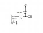
On a lighting system for a radio controlled airplane, the Picaxes will be reading pulses from the RC receiver. The receiver will be powered with a LiFe battery (peak charge is 6.7V). The Picaxes power is 5V (with LM7805 regulator). My concern is whether the RX pulses (potentially 6.7V) will damage the microprocessors.
The attached PDF file has the schematic.

Andrés
 

Attachments

srnet

Senior Member
It will damage the PICAXE unless you protect the pin.

A 22k resistor in line with the signal from the RC receiver should be enough, the input pins of the PICAXE have clamp diodes on them and the resister will limit the current through this diode to a safe value.

Are you sure the receiver itself can cope with 6.7V ?

5V is the common limit and some receivers can work at 6V.
 

Goeytex

Senior Member
While a 22K resistor alone should work ok, a Zener clamp will work better than the internal ESD diodes. The BAT85 will clamp the Voltage to about 5.2 volts while the internal ESD diodes will clamp the voltage to about 5.5volts. Attached is how I would do it. One resistor and one external diode will provide protection for both Picaxe Chips.
 

Attachments

tony_g

Senior Member
=srnet

Are you sure the receiver itself can cope with 6.7V ?
most rc recievers now can take a wide input voltage, my spektrum is rated for 3.3v to 9.6v on the rx side.
 
Thank you for the replies gentlemen.
I added the resistor and the diode and things are working fine. The RX was powered in the past with a 2 cell LiPo with no problems, the voltage does not bother the servos either. My concern was the Picaxe chips.

Andrés
 

Paix

Senior Member
Slip of the pen probably, but
a Zener clamp will work better than the internal ESD diodes. The BAT85 will clamp the Voltage to about 5.2 volts
BAT85 is a Schottky barrier dode and not a zener as appears to be cited. It has a lower forward voltage drop than a ubiquitous 1N4148 or 1N914 for example.
 

tony_g

Senior Member
i run my rx at 5v as i dont need to use H.V servos running above that but just out of curiosity i put my multimeter to the ground and signal output of the aux channel i normally use to activate my circuits, i bumped up the rx input voltage to 6v and then 7.4v and read the rx signal out as 0.18v at low position,0.28v at mid and 0.38 at high position.

my circuits run from the rx at 5v as stated and have the inline 330R resistor from the aux channel to picaxe input but i am supprised the metered output from the rx at the stated higher input voltages is as low as it is in the outputted positions.

interesting as the question for this thread was with concern to a higher input voltage on the rx and the output signal potentially being above the max voltage of the picaxe i am supprised to just get those readings from my rx being as low as they are
 

rossko57

Senior Member
out of curiosity i put my multimeter to the ground and signal output of the aux channel i normally use to activate my circuits, i bumped up the rx input voltage to 6v and then 7.4v and read the rx signal out as 0.18v at low position,0.28v at mid and 0.38 at high position.
It's a stream of pulses. Unless your multimeter is something special, it is only showing the _average_ voltage of a stream of high pulses and low gaps.
 

Paix

Senior Member
Nah, Tony_g, we'll be happy to testify that you need an oscilloscope. It will have to be a PC Santa Scope from Tech Supplies mind you, I don't think we have enough influence to support a Rigol . . .
 

Paix

Senior Member
@tony_g, Erco - my purchasing manager adopt' has me sending all my pocket money to China for goodies. My postman is under the illusion that the Royal Mail must be doing extremely well . . .
 
Top