I received several INHAOS LC-1000 RF Transceiver modules a while back and have finally gotten around to testing them with a Picaxe. They work amazingly well for short range RF comms.
The main challenge for the hobyist is to get wires/ connectors on to the LC-1000 module. The pad spacing is only 1.27mm so soldering leads or a connector will require a fine tip soldering iron, solder flux, and a big magnifier. I used 28ga stranded hookup wire. My units were supplied with a 1.27mm spaced male header that was not installed. However a search for a 1.27mm female connector/header was fruitless. INHAOS should consider the option of the installing the header on the module and supplying a connector with flying leads. Another option might be a breakout board with 2.54mm pin spacing.
The LC-1000 operates in the 2.4 Ghz ISM band. It transparantly uses frequency hopping / clear channel assessment across the band so crowded channels and channel selection are not something the user needs to be concerned with. It is all done seamlessly via the RFIC and MCU.
Each module has a unique ID or address that is laser etched on the body of the RF shield. A sticker on the shield indicates the factory programmed link address, which is the address of the other module to communicate with. At power on the both of these addresses are loaded from the modules EEPROM and the module does handshake.to establish an RF link with the module at the programmed link address. Once linked, serial data sent from one module is received by the other module and is then sent out receiving module's TX pin.
LC-1000 can be programmed to change several parameters
1. Local_Address (64 bit address)
2. Link_Address (64 bit address)
3. Serial Baud Rate (2400 to 57600)
4. Sleep_time (0 to 65535 seconds)
5. Working Mode (Sleep or normal)
All of these settings can be saved to the module's EEPROM except the Local Address. This is not noted in the Datasheet. The local address can be changed within a program if necessary, but that change will be lost either after a "hard reset" or soft reset LC-1000 module. It will then revert back to the UID etched onto the module.
The Datasheet also shows a Carrier setting which implies that the RF channel can be changed by sending command $EF to the module. Don't use this command. This command is ONLY for engineering use and FCC testing with a spectrum analyzer. IF you use this command the module will stop working until the power is cycled off / on.
The LC-1000 uses automatic frequency hopping ( also not clearly stated) so manually changing channels is not necessary or supported. The RF channel is automatically determined by the LC-1000.
There is no configuration utility provided specifically for the LC-1000. However, configuration can be done through a terminal program or with Picaxe Basic Code. I have included examples in the Demo Program that gives shows how to do this.
Serial communication to and from the Lc-1000 is always non-inverted and 8,N,1. The baud is determined by the baud setting in the LC-1000 EEPROM or by the last baud command. Once the baud rate is changed, whether or not the change is save to EEPROM the module will only communicate at the new baud rate. The default power up baud rate is 9600. However if it has been changed and the change saved to LC-1000 EEPROM, it will power up at the changed rate. The baud rate can always be reset to 9600 by powering down the LC-1000 and holding the config pin low for > 200ms while powering the module back up.
There are 12 valid commands for changing & reading the configuration settings. To set or read a setting the config pin must be taken low and then a 13 byte packet sent to the module's RX pin.
The packet is in the format of :
Checksum, save_byte, command, num_bytes, val_1,val_2,val_3,val_4,val_5,val_7,val_7,$0D,$0A)
The checksum can be computed in Picaxe BASIC as:
The save byte determines if the register setting value(s) is saved to the LC-1000 EPROM or not. The save byte is ignored with CMD $FO. Valid commands are $CE,$CF, $F0 through $F5 and $D0 through $D5. Do not use $EF listed in the datasheet on page 17. $EF is for testing/validation only and using it will cause the LC-1000 to stop working properly until reset.
Read Commands:
$CE Read Device Type 7 bytes
$CF Read Firmware Ver 2 bytes
$D0 Read Local Addresss 4 bytes
$D1 Read Link Address 4 bytes
$D2 Read Baud Rate 2 bytes
$D3 Read Sleep Time 4 bytes
$D4 Read Work Mode 1 byte
$D5 Read RF Power Level 1 byte
Write Commands:
$F0 Set Local Address ( save byte is ignored)
$F1 Set Link Address
$F2 Set Baud Rate
$F3 Set Sleep Time
$F4 Set Work Mode
$F5 Set RF Power Level
After receiving a valid command packet with the correct checksum, the LC-1000 will reply with it's own 13 byte reply packet. The packet will be in the same format as the one sent. If the packet received is valid, the LC-1000 will return 13 bytes, one of which is the command byte. If there is an error, the cmd byte will be returned as either $E1 (invalid command) ,$E2 (bad checksum) ,or $E3 ( Invalid Data). The demo code does not check the reply for errors. This can be added if needed.
The settings that will most likely need to be changed are link_address and baud_rate. Examples are included in the Demo Program
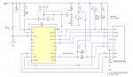
Attached is a Demo Program and a schematic. The demo program uses a Picaxe 20X2 for wireless chat between 2 PC's. The Picaxes were used to add
add some bells and whistles to allow use of the Picaxe Terminal and to allow programming and chatting without having to add a second serial port or USB TTL module.
The schematic includes a 10K thermistor that connects to an ADC input. A loop can be added to the code to wirelessly transmit the ADC value (Temperature) to a PC or even to a stand alone unit.
This demo program should give a good idea how to use the LC-1000 and should offer a foundation for more complex applications.
I used Picaxe 20X2's for interfacing to the LC-1000. The main reason being the capability of hardware background receive which is fast and allows for dynamic packet lengths and a circular receive buffer if needed. However the LC-1000 will work fine with M2 Picaxe chips, but the code and connections will need to be modified.
Enjoy
The main challenge for the hobyist is to get wires/ connectors on to the LC-1000 module. The pad spacing is only 1.27mm so soldering leads or a connector will require a fine tip soldering iron, solder flux, and a big magnifier. I used 28ga stranded hookup wire. My units were supplied with a 1.27mm spaced male header that was not installed. However a search for a 1.27mm female connector/header was fruitless. INHAOS should consider the option of the installing the header on the module and supplying a connector with flying leads. Another option might be a breakout board with 2.54mm pin spacing.
The LC-1000 operates in the 2.4 Ghz ISM band. It transparantly uses frequency hopping / clear channel assessment across the band so crowded channels and channel selection are not something the user needs to be concerned with. It is all done seamlessly via the RFIC and MCU.
Each module has a unique ID or address that is laser etched on the body of the RF shield. A sticker on the shield indicates the factory programmed link address, which is the address of the other module to communicate with. At power on the both of these addresses are loaded from the modules EEPROM and the module does handshake.to establish an RF link with the module at the programmed link address. Once linked, serial data sent from one module is received by the other module and is then sent out receiving module's TX pin.
LC-1000 can be programmed to change several parameters
1. Local_Address (64 bit address)
2. Link_Address (64 bit address)
3. Serial Baud Rate (2400 to 57600)
4. Sleep_time (0 to 65535 seconds)
5. Working Mode (Sleep or normal)
All of these settings can be saved to the module's EEPROM except the Local Address. This is not noted in the Datasheet. The local address can be changed within a program if necessary, but that change will be lost either after a "hard reset" or soft reset LC-1000 module. It will then revert back to the UID etched onto the module.
The Datasheet also shows a Carrier setting which implies that the RF channel can be changed by sending command $EF to the module. Don't use this command. This command is ONLY for engineering use and FCC testing with a spectrum analyzer. IF you use this command the module will stop working until the power is cycled off / on.
The LC-1000 uses automatic frequency hopping ( also not clearly stated) so manually changing channels is not necessary or supported. The RF channel is automatically determined by the LC-1000.
There is no configuration utility provided specifically for the LC-1000. However, configuration can be done through a terminal program or with Picaxe Basic Code. I have included examples in the Demo Program that gives shows how to do this.
Serial communication to and from the Lc-1000 is always non-inverted and 8,N,1. The baud is determined by the baud setting in the LC-1000 EEPROM or by the last baud command. Once the baud rate is changed, whether or not the change is save to EEPROM the module will only communicate at the new baud rate. The default power up baud rate is 9600. However if it has been changed and the change saved to LC-1000 EEPROM, it will power up at the changed rate. The baud rate can always be reset to 9600 by powering down the LC-1000 and holding the config pin low for > 200ms while powering the module back up.
There are 12 valid commands for changing & reading the configuration settings. To set or read a setting the config pin must be taken low and then a 13 byte packet sent to the module's RX pin.
The packet is in the format of :
Checksum, save_byte, command, num_bytes, val_1,val_2,val_3,val_4,val_5,val_7,val_7,$0D,$0A)
The checksum can be computed in Picaxe BASIC as:
Code:
Checksum  = save + cmd + numbytes + val_1 + val_2 + val_3 +val_4  + val_5  +val_6 +val_7 + 13 + 10
Checksum = NOT ChecksumRead Commands:
$CE Read Device Type 7 bytes
$CF Read Firmware Ver 2 bytes
$D0 Read Local Addresss 4 bytes
$D1 Read Link Address 4 bytes
$D2 Read Baud Rate 2 bytes
$D3 Read Sleep Time 4 bytes
$D4 Read Work Mode 1 byte
$D5 Read RF Power Level 1 byte
Write Commands:
$F0 Set Local Address ( save byte is ignored)
$F1 Set Link Address
$F2 Set Baud Rate
$F3 Set Sleep Time
$F4 Set Work Mode
$F5 Set RF Power Level
After receiving a valid command packet with the correct checksum, the LC-1000 will reply with it's own 13 byte reply packet. The packet will be in the same format as the one sent. If the packet received is valid, the LC-1000 will return 13 bytes, one of which is the command byte. If there is an error, the cmd byte will be returned as either $E1 (invalid command) ,$E2 (bad checksum) ,or $E3 ( Invalid Data). The demo code does not check the reply for errors. This can be added if needed.
The settings that will most likely need to be changed are link_address and baud_rate. Examples are included in the Demo Program
Attached is a Demo Program and a schematic. The demo program uses a Picaxe 20X2 for wireless chat between 2 PC's. The Picaxes were used to add
add some bells and whistles to allow use of the Picaxe Terminal and to allow programming and chatting without having to add a second serial port or USB TTL module.
The schematic includes a 10K thermistor that connects to an ADC input. A loop can be added to the code to wirelessly transmit the ADC value (Temperature) to a PC or even to a stand alone unit.
This demo program should give a good idea how to use the LC-1000 and should offer a foundation for more complex applications.
I used Picaxe 20X2's for interfacing to the LC-1000. The main reason being the capability of hardware background receive which is fast and allows for dynamic packet lengths and a circular receive buffer if needed. However the LC-1000 will work fine with M2 Picaxe chips, but the code and connections will need to be modified.
Enjoy
Attachments
-
 29.9 KB Views: 54
 -
8.5 KB Views: 15
Last edited:
")