PCB scope - a present from Santa?

crowland

Member
Nah, This http://www.thevalvepage.com/testeq/cossor/1049/1049.htm is an oscilloscope! :)

But yes, the DP scope is a real scope, and better performance than my 1049 as well.

Back in the 60s I was trying to make radios with one OC71 transistor.

I did make a radio controlled Dalek, the sensation it caused at school was immense.

Listening to the Voice Of America (in Basic English) and Radio Moscow, who explained there was no heaven - they sent Gagarin and Titov up to see.

Listening to John Glenn in orbit, he was talking about fly by wire and I was wondering why the air didn't leak out round the wires.

Nowadays I'd give my 13 yo self some Picaxes, motors, servos, sensors and switches, some stuff to hang it all together, and stand well back. A well stocked first aid kit would be a good idea.

Chris
 

RonnS

Member
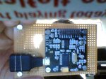
ok,,,,,, my PCB scope is arrived today..but i am crying.. in My House is an Micro USB Cable not available..so i look at
these connection i think thats not the best...i hope changed with the next revision

happy new year.. Ron, from Germany
 

Buzby

Senior Member
Hi Chris,

I had three of these when I was in my teens. Two were fairly normal, but the third was a weirdo with a really slow timebase ( 10's of seconds per div ), with the ability to trigger from a volt-free contact.

It's good to see them again on the Internet, but one thing you can't get online is the smell of hot air from all those valves.

It's been so long ago I can't even remember where the scopes went, never mind where they came from. I just remember the inside of my shed looked like the set of a 1950's Sci-fi film.

Reminiscing again,

Buzby

EDIT : I had one of these as well : http://www.thevalvepage.com/testeq/cossor/1039m/1039m.htm
 
Last edited:

john2051

New Member
Hi Buzby, funny you show the 1039m, I have one in my attic in perfect working order. It even still has the
twin cotton covered mains lead with two pin plug.
Its strange though, I've got a four channel 300MHz fluke scope that cost alot; yet my 10MHz hand held lcd
scope gets far mor use. When i was at college there were several large tek scopes on trolleys, and when they were all
active you didn't need any heating on!
These little scope boards are quite usable though. I think for the sake of sturdiness with that usb connector i will use
one of the raspberry pi panel mounted usb to micro usb cables, and mount the board in one of the hammond metal
cases..
regards john
 

ZOR

Senior Member
I intend to mount my scope pcb onto a sub board and put it in a case. Then I will use a suitable cable which will plug unto the scope pcb and be held in place to the sub board with a pclip.

The other end of the cable will have a panel mouned socket, into which a lead can plug into and then into my PC's USB.

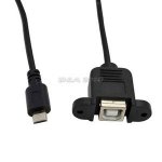
I have looked at this cable, however can somebody say if it will be compatable, hope so because the termination cable to the PC will be much more robust.

http://cgi.ebay.co.uk/ws/eBayISAPI.dll?ViewItem&item=400525336461&ssPageName=ADME:L:OC:GB:1120

LEAD.JPG

Appreciate an answer, thanks
 
Last edited:

srnet

Senior Member
in My House is an Micro USB Cable not available..so i look at
these connection i think thats not the best...i hope changed with the next revision
I guess they chose the Micro USB as its so common.

Although I think they actually mean the Micro B USB (as on most new phones these days) but to me those don't look that durable.
 

Brian M

Member
You're right on the Micro B USB socket mounted on the DPScope. It is very delicate, as I know to my cost, and being clumsy when mounting it in the Maplins case shown earlier. The fault was all mine being to eager to get it cased and not paying enough attention to not putting any strain on the socket with cable attached.

Cost of repairing it was the cost of a new DPScope from Tech Supplies. The new one is now mounted in it's housing with 2 BNC sockets fitted and awaiting a connector for the datalogger.

My installation of the PCB is similar to that of "Electlen". Tip - If you are going to mount your scope in a box like this. Fit the posts in the box and then, with the cable attached and the entry point on the box correctly engineered, drop the PCB + Cable onto the posts and secure.

That USB socket is not forgiving, so don't rush it (Like wot I did), think it out and take care.

Fortunately had to take my daughter back to Bath University, so calling in to collect me repeat order wasn't a problem.

Now got a handy little device, which should be put to good use.
 

Brian M

Member
Ref #85 - Why not just something like this:

http://www.ebay.co.uk/itm/USB-2-0-A-Male-To-B-Micro-USB-Data-Sync-Cable-Charger-Lead-For-Mobile-Phones-/181120943960?pt=UK_MobilePhones_MobilePhoneAccesories_MobilePhoneDataCables_JN&hash=item2a2ba64758

This is just a one lead connection to your PC usb socket unless you only have the USB shown in your lead.

You can't go far wrong copying Electlen's build. It's a neat little self contained unit. Just assemble the board c/w lead and drop it onto the fixings. The way he has used the body of the Micro USB to anchor the cable does the job just fine.

I don't believe the PC end is the delicate connection, more the scope micro usb end, which Electlen's method deals with.
 
Last edited:

ZOR

Senior Member
Thanks Brian,

I just wanted to have a small box with 2 BNC's on and output socket into which I can plug in an interconnecting cable from my scope to PC. The panel mounted socket in the picture is far more robust compared to the mini USB sockets. I just do not know whether this lead can be used. I will lose the mini USB to panel mount socket lead within my case.
 

ZOR

Senior Member
Same here Jim, I have ordered both cables, cheap enough, looks like the only way is to try. Again will wait from China for the one I was looking at first.
 

ZOR

Senior Member
Thanks John, yes I saw them. I would rather wait than make someone rich buying from China and selling on Ebay??
 

john2051

New Member
Hi Zor,
I suppose I agree, however I'm not gifted with patience! Also, some time ago i ordered 4 rtc boards from china,
I 'm still waiting.
regards john
 

Paix

Senior Member
I keep a check of anything in flight on the China slow boat and the track record has been good, although some items travel a lot slower than others. It is rare for anything to exceed thirty days in my experience. Others haven't been as lucky perhaps.
 

rq3

Senior Member
I keep a check of anything in flight on the China slow boat and the track record has been good, although some items travel a lot slower than others. It is rare for anything to exceed thirty days in my experience. Others haven't been as lucky perhaps.
As a wee lad in the late 60's I requested a ferrite pot core sample from Seimens in Germany. I needed it to build a proton spin magnetometer from "The Amateur Scientist" in "Scientific American" magazine. When it arrived 2 YEARS later, I'd forgotten what it was for. Still have it.

Rip
 

ZOR

Senior Member
Gonna get shot soon for deviating from Picaxe, but all my China purchases have been full filled. If on rare occasion nothing arrived they were only too pleased to re-post out. They always showed a high regard on their own service. May the Chinese continue to supply us with goodies.
 

Paix

Senior Member
I have only had one occasion when I have politely enquired about the status due to delay and the postmark suggests that it was quickly sent or resent, but very polite and giving the impression generally that business is keen and potential repeat business and reputation was valued.
 

Paix

Senior Member
It's not the first time someone in the UK has been prosecuted for having a bedroom full of undelivered bags of mail. Full marks to my postmen as they battle through the rain like ducks.
 

Paix

Senior Member
Speaking to a friend on the radio yesterday evening, also a prospective Santa Scope customer if he hasn't ordered already, I had mentioned about the micro USB connector, but we were talking at the time of work he was doing with his Raspberry Pi. He commented that the micro USB on that device was beginning to show signs of wear and tear and would be looking to power it from a header instead.

I guess that Micro USB connectors are a form of unexpected built in maintenance which will inevitably reduce the useful life of some bits of kit if extra care isn't lavished upon them. It all seemed such a good idea at the time. Smaller, better . . . :)
 

MFB

Senior Member
I guess its only a problem if you really need a cable that disconnects at both ends. Otherwise, just protect the micro USB connector by the liberal application of glue to the board and make do with a fixed flying lead to the PC.
 

MLPINTO

New Member
OSC001. My solution.

I purchased OSC001. The solution for the USB connector I have taken, showing on the picture. This I avoid the fragile micro connector.
Snapshot_20140212_1.JPG
 

g0rph

New Member
Good Morning All,

Hopefully I am doing this right, as it is my first post!

I have been playing with a friends PCB Scope (before buying my own) and have found it most impressive for the small outlay.

I have tried out most of the functions OK, but have noticed that when using 10:1 probes in oscilloscope mode, the software compensates for the "DC offset" very nicely, by means of the tickbox, but the "CH 1" trigger setting is not offset to match. Consequently if operating in "CH 1" trigger mode, the trigger levels are offset from the waveform (but otherwise work correctly). Is this a bug in the software or am I doing something wrong?

Look forward to your comments,

Richard.
 

womai

Senior Member
The trigger input gets the same offset-corrected signal so this is not supposed to happen. I'll need to look into this and will let you know if I find anything.

As a side note, due to the way the circuit works you can only compensate (adjust) the offset for either 1:1 or 1:10 probes, but not both at the same time.
 

g0rph

New Member
Thanks for the very quick reply, Womai!

When using the probes I have set both channels to 10:1 (and used a single 10:1 probe, changing it, as required, between the two BNC connectors which are fitted to my friends unit).

Richard
 

womai

Senior Member
Ok, that was indeed a bug - just fixed it. Also discovered that there were a couple other things messed up in 1:10 mode - cursor and measurement scaling. Also 1:10 mode really only makes sense for 5V/div and above. Fixed all these as well.

Download the new version (V1.0.5) from here:

http://www.pdamusician.com/dpscope/files/DPScopeSE10.zip

After install, check the About window, should say V1.0.5 for the PC software, with a build date of 2014-02-23.
 

JimPerry

Senior Member
Updated software - now get USB device not recognised messages and initially could not find DPScope - then software starts with Run greyed out. Did work fine before new version ... Windows 7 pro 64bit 16GB RAM :(

Reverted to original version and now working again :rolleyes:
 
Last edited:

womai

Senior Member
DPScope or DPScope SE? (these are two different instruments and use different software). The updated software above is for the DPScope SE. I just checked it on all of my PCs and it runs and connects fine on all of them...
 

JimPerry

Senior Member
The Rev-Ed "Santa" scope. There was a brief error message about not being able to write an OCX file a few times.:confused:
 

womai

Senior Member
You could use Winzip to just extract DPScopeSE.exe from the CAB installer and use it to replace the old DPScopeSE.exe ind the programs folder. (of course make a backup of the old file before :=) That way you d not have to (re-)install any of the ActiveX controls that give you grief.
 
I am thinking of buying this Scope (I am assuming that this is the Scope that I saw on www.picaxe.com) as appears to be really good. I was wondering if there was a "Kit" to buy to furnish a suitable enclosure and BNC connectots.
Also, for the logic analyser part, what are good connectors for the ports?
I want to end up with a finished unit with proper connectors and proper leads....
Thanks for any help.
Regards
Andy
 

StigOfTheDump

Senior Member
I have the DPScope SE in a case, that I bought last year. For the analyser port I replaced the row of header pins with a 16 pin ribbon cable connector with one row of the pins taken out. I find it works very well.
 

John West

Senior Member
der_fisherman, Andy, there are 2 versions of this scope with the same electronics and software, but different physical configurations and price. It sounds like you are describing this one: http://www.pdamusician.com/dpscope/overview_se.html, the PDScopeSE as the one to meet your needs.

Your link didn't take me directly to the version offered by Rev. Ed. but I'm assuming it's the surface mnt, pre-assembled bd version OSC001 that this thread is about, that doesn't include any of the extra hardware and packaging you describe. This version of the scope is sold by Rev. Ed. at an extremely low price, obviously more as a service to PICAXE customers and hobbyists than as an income-producing product.

For that matter, the PDScopeSE version isn't sold at much of a profit either. Either version is a great value. Which one you choose depends on what you want to do with it. The Rev. Ed. version was intended to be plugged into a prototyping bd to be used while you were trying out a new design idea you were prototyping, or doing experiments on the plug-in bd.

The PDScopeSE version is much more rugged and handy for carrying around with your tools and plugging into a laptop PC to take 'scope measurements wherever you need to.
 
Last edited:

g0rph

New Member
Hello Womai,

Thanks for identifying and fixing that bug, it now works just as I expected it should! (I have only just got round to testing it as I have been away)

It is also most helpful that the displayed V/div now changes when the 1:10 is selected, so that there is no mental arithmetic required.

I would however disagree with your "Also 1:10 mode really only makes sense for 5V/div and above." for the following reasons: If working on a circuit which has both high level (perhaps 50V) and low level (maybe 1V) signals, it is a great nuisance to keep changing probes AND to do so also loses the advantage of 10Mohm input impedance for the lower signals, just where (audio) circuit impedances are likely to be highest! If at all possible, it would be nice to have the 1:10 facility on ALL the input ranges, as you do on a conventional analogue scope. Switchable probes get around the former, but not the latter, and there are lots of non-switchable probes about anyway.

If it's not possible on all ranges, then even re-instating the 2V/div range would be good?

What do you think?

Best regards, Richard.
 
Top