Pinewood Derby Stopwatch/Timer

AlbertZ

Senior Member
First a word of introduction because I am new to this forum. I am a 72 year old retired mechanical engineer. During the spring, summer and fall my passions are fishing and giant scale radio control airplanes. During the winter I revert back to my interest in electronics. I earned my FCC license before I earned my driver’s license. I have successfully built the following Picaxe projects: servo tester, simple robot, towers of Hanoi, LED cube. The programming was a result of cut and paste then hacking until I got the things to work. Therefore let it be known at the outset that I am not a programing whiz.

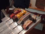
This winter I would like to build a stopwatch/timer accurate to 0.01 seconds. The inspiration came from involvement in my grandson’s cub scout Pinewood Derby event. Simply described, a group of wooden cars are released, roll down a ramp then on to a straightaway with a finish line at the end.

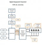
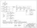
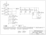
The attached block diagram illustrates where my thought process lies at this point in time. The oscillator section derives a series of 100 Hz pulses, thus 10 pulses = 0.1 sec, 15 pulses = 0.15 sec, 615 pulses = 6.15 seconds, etc.These pulses would be delivered to a microprocessor which would serialize the information and deliver it to a multiplexed LED display driver. The start of the timing sequence would be initiated by a limit switch at the starting gate. The end of the timing sequence would be determined when the car interrupts a photocell. Reset would be a simple push button.

I would appreciate any and all thoughts on the subject and any suggestions for changes at this stage of the game will be welcome.
 

Attachments

eclectic

Moderator
Welcome to the Forum.

I've moved your post to the
Active Forum area.

May I suggest a quick look at the
Advanced Search facility
(Upper right on this page).

There is plenty of information and expertise available.

e addit.

Flowchart as jpg
 

Attachments

Rick100

Senior Member
Hello AlbertZ . That looks like a fun project . I think the picaxe is fast enough to count the clock signals . Do you intend to update the display while the car is running or just display the final time ? Are you going to expand it later to more than one car ?
I was reading through some old Nuts & Volts 'Basic Stamp' articles the other day and found Scott Edwards articles on a Pinewood Derby timing system . Here is a link to zip file containing them . Parallax makes the old articles available to the public .
http://www.parallax.com/downloads/nuts-and-volts-basic-stamps-volume-1
The Pinewood articles are in NV21.pdf , NV22.pdf , and NV24.pdf . They are for a BS1 but most of the code is usable .

Good luck,
Rick
 

erco

Senior Member
Welcome AlbertZ! Great project. Sounds like you're well on your way already. How many lanes are you timing? You want just the winning time, or the time for each lane? At a minimum, you need a winning lane indicator and single time display.

You can simplify from your block diagram. I go for the simplest solution. If I did this, I'd use a 20M2 for the most pins (future expansion) and just let that do the timing. With some careful calibration, you can get accuracy down toward the 0.01 second range. Even if it's off somewhat, it will be consistent (error will self-cancel) for all cars on the track. You'll want to use an IR emitter and phototransistor since photocells have slower response.

And if you pick the right LED display, you can drive that directly from the 20M2, which will use a few extra pins. All the more reason to use a 20M2.
 

Roman505

Member
Not saying this is less effort than any other solution but one that occurred to me is to use an ordinary clock chip like the DS1307. Have it interrupt the Picaxe every second and leave Picaxe to count hundredths between those interrupts. The Picaxe counts only in 10 mS intervals without error accumulating beyond 1 S or 100 counts. It gives a measure of calibration-by-reset without having to worry too much about tuning the Picaxe timing or to use a crystal and mutliple dividing chips.
 

techElder

Well-known member
AlbertZ, make the best, fastest and most stable gated-counter that you can possibly make. Store the elapsed time locally. Test it under "extreme" conditions for your sport. Then replicate it for each lane. Perhaps this is designed based on an 08 PICAXE.

Then and only then build a display station that polls each timer and displays the results of each.

You won't regret this method. It is modular for many reasons, the least of which maintenance. Maintenance will kill your solution quicker than uttering expletives in front of "the children."
 

AlbertZ

Senior Member
Welcome AlbertZ! Great project. Sounds like you're well on your way already. How many lanes are you timing? You want just the winning time, or the time for each lane? At a minimum, you need a winning lane indicator and single time display.

You can simplify from your block diagram. I go for the simplest solution. If I did this, I'd use a 20M2 for the most pins (future expansion) and just let that do the timing. With some careful calibration, you can get accuracy down toward the 0.01 second range. Even if it's off somewhat, it will be consistent (error will self-cancel) for all cars on the track. You'll want to use an IR emitter and phototransistor since photocells have slower response.

And if you pick the right LED display, you can drive that directly from the 20M2, which will use a few extra pins. All the more reason to use a 20M2.
The project is starting to come into clearer focus keeping in mind my limited programming skills. Let’s start by defining the parameters. We need to measure the time for three separate lanes. An order of finish display would be nice but not absolutely necessary. The duration of each race is typically less than 5 seconds.

A single limit switch would start timing the race and interrupting the light to individual photo-transistors would end the timing for each lane. All the tracks would utilize a single limit switch to initiate timing.

My thinking is to mount the 18M2 on a Xino board (I have a couple of these) and then build a shield to interface with the Xino that would contain the oscillator section and CD4066. I would have to build three display modules containing the 74C926 driver and 7-segment displays.

Since the duration of these races is less than 5 seconds, it makes no sense to have two digits in front of the decimal place. Why not reconfigure the second 74LS390 (IC3) as a divide by 2/divide by 5 counter so that the output is 1000 Hz instead of 100 HZ? Then I could display the time to 3 decimal place accuracy.

The advantage to this configuration is that all of the timing is done outside the PICAXE, so all it need concern itself with is logic. The 18M2 has plenty of extra I/O so it would be a simple matter to add another 7-segment display and cheap driver (4026) to display the order of finish.

As far as programming is concerned, it should be a matter of defining the constants and variables, then developing the logic which should consist mostly of “if…..then” and “for….next” statements. There is plenty of code available to cut and paste, then hack until I get it to work. PICAXE provides a nice little simulator to help debug the programs. Remember, the programming language is BASIC, not hex or C, so this should be within my limited capabilities.

I realize that there are more elegant display configurations, but I want to keep this within my programming skill set. This is a winter project and I will have to re-learn most of the programming knowledge that I acquired last year from previous projects. The same applies to timing. I’ve seen this technique used before. It’s cheap and accurate.
AsTexasclodhopper suggests, I plan to build this In modular form starting with the timing section first. Each module will be breadboaded before etching any boards.
 

Attachments

erco

Senior Member
A cheap LED display like this is easy to use directly with logic lines, it has transistor drivers for each segment built-in: http://www.ebay.com/itm/RED-4-Bit-8-SEG-LED-Display-Board-Parallel-Digital-Tube-Display-Module-/400427457742?pt=LH_DefaultDomain_0&hash=item5d3b561cce#ht_4025wt_932

With a little creative labeling & a visual barrier, you could use this 4-digit readout to display one digit for which lane won, and 3 digits for your timer display with DP. That would use 11 output lines, so you would want to use a 20M2.
 

AlbertZ

Senior Member
A cheap LED display like this is easy to use directly with logic lines, it has transistor drivers for each segment built-in: http://www.ebay.com/itm/RED-4-Bit-8-SEG-LED-Display-Board-Parallel-Digital-Tube-Display-Module-/400427457742?pt=LH_DefaultDomain_0&hash=item5d3b561cce#ht_4025wt_932

With a little creative labeling & a visual barrier, you could use this 4-digit readout to display one digit for which lane won, and 3 digits for your timer display with DP. That would use 11 output lines, so you would want to use a 20M2.
Nice! But I wish the male header was on the other side of the board. These need to mount on a bridge above each race lane.
 

AlbertZ

Senior Member
Welcome AlbertZ! Great project. Sounds like you're well on your way already. How many lanes are you timing? You want just the winning time, or the time for each lane? At a minimum, you need a winning lane indicator and single time display.

You can simplify from your block diagram. I go for the simplest solution. If I did this, I'd use a 20M2 for the most pins (future expansion) and just let that do the timing. With some careful calibration, you can get accuracy down toward the 0.01 second range. Even if it's off somewhat, it will be consistent (error will self-cancel) for all cars on the track. You'll want to use an IR emitter and phototransistor since photocells have slower response.

And if you pick the right LED display, you can drive that directly from the 20M2, which will use a few extra pins. All the more reason to use a 20M2.
A great number of people tell me that a PICAXE is too slow to do the timing to 1 ms resolution as well as handle the logic for three separate race lanes. That is why I am keeping the clock signal out of the PICAXE and routing it through the CD4066.

I read in the data sheets that the PICAXE can process up to 4 tasks simultaneously. Is this true? How? Could we process the logic for each lane separately? Would this speed things up?

I could simplify the display considerably by using a MAX7219. Since I have to build three of these I can see that as a great advantage, especially if the display has the current limiting resistors integrated. But this means a lot more lines of code which I'm not sure I am up to. Could someone help me with this part?
 

AlbertZ

Senior Member
I think I finally have this worked out. It seems to work well on the simulator so the next thing is to breadboard it.

Oscillator

IC1, IC2 and IC3 comprise the oscillator section which generates a 1 kHz signal which is routed to each of the display modules.

Initial Conditions

The start gate is in the normally closed position, that is, the stops that keep the cars from running are in the UP position. A limit switch configured as NC/NO is mechanically attached to the starting gate shaft. The starting gate is typically held closed with spring tension or rubber bands. A cam on the shaft keeps the limit switch contacts closed.
When the starting gate is lowered, the cam has a notch which allows the limit switch to momentarily open at the same time that the cars are released. This allows B.3 to go LOW and initiates the timing cycle by opening the gates on the CD4066 and allows timing in each lane to begin.

During the Race

As long as the photo-transistors Q1, Q2 and Q3 are conducting, the inputs B.0, B.1 and B.3 remain LOW. When the light beam is interrupted, the transistors stop conducting and the inputs go momentarily HIGH. The program continuously polls these inputs and when they detect a HIGH they cause the corresponding output on port C to go low thus recording the time for that lane.
Hybrid Digital Stopwatch Oscillator Rev 1_1.jpg
 

Rick100

Senior Member
Oscillator

IC1, IC2 and IC3 comprise the oscillator section which generates a 1 kHz signal which is routed to each of the display modules.
You could use the pwmout command to generate the 1 kHz signal . The picaxe editor has a wizard for setting it up.
 

vttom

Senior Member
Have you considered using an output of the PICAXE to drive a servo or solenoid to drop the starting gate (using a PICAXE input to sense a button press to start the race)? Seems to me this would be a more accurate and consistent way to start the race than sensing when the gate is manually opened by a human operator.
 

AlbertZ

Senior Member
You could use the pwmout command to generate the 1 kHz signal . The picaxe editor has a wizard for setting it up.
I'll investigate and see if it would work in this application. I have not been able to find timer projects that measure to three decimal places using PICAXE. The problem is processor speed, or so I have been led to believe.

Incidentally, how do you go about posting code in this forum?
 

AlbertZ

Senior Member
Have you considered using an output of the PICAXE to drive a servo or solenoid to drop the starting gate (using a PICAXE input to sense a button press to start the race)? Seems to me this would be a more accurate and consistent way to start the race than sensing when the gate is manually opened by a human operator.

Not necessary. This is the way it's done in thousands of venues around the country. The attached photo shows a 4-lane set-up. Our cub scout pack has a 3-lane setup. By adjusting the cam to coincide with when the cars start moving gives a close enough result. Pinewood_Derby_Start.jpg
 

Rick100

Senior Member
I have not been able to find timer projects that measure to three decimal places using PICAXE. The problem is processor speed, or so I have been led to believe.

Incidentally, how do you go about posting code in this forum?
The pwmout command uses the pic hardware to produce the signal continuously in the background. It will not slow down your program.
The command 'pwmout pwmdiv4, B.6, 249, 500' will produce a 1 kHz 50% duty cycle square wave on pin B.6 of an 18M2 running at 4 MHZ. I'm not sure of it's accuracy. To post code in the forum , use the # button in the advanced reply window to wrap selected text with
Code:
 tags. You can also use the 'copy to forum' item in the Picaxe editor to wrap selected code with the [CODE] tags and place it in the clipboard.

Good luck,
Rick
 

AlbertZ

Senior Member
The pwmout command uses the pic hardware to produce the signal continuously in the background. It will not slow down your program.
The command 'pwmout pwmdiv4, B.6, 249, 500' will produce a 1 kHz 50% duty cycle square wave on pin B.6 of an 18M2 running at 4 MHZ. I'm not sure of it's accuracy. To post code in the forum , use the # button in the advanced reply window to wrap selected text with
Code:
 tags. You can also use the 'copy to forum' item in the Picaxe editor to wrap selected code with the [CODE] tags and place it in the clipboard.

Good luck,
Rick[/QUOTE]

Thanks! If the internal resonator is anywhere close to the accuracy of an external regulator, this should work just fine and would eliminate 3 chips.  Thanks again for the tip.  Time to experiment.

Al
 

AlbertZ

Senior Member
Here is the code for my initial design using an external oscillator. The text output is there only to verify operation in the simulator. This is my first attempt at writing code from scratch, so if there is a more efficient way to do this all suggestions are welcome.

Code:
'=======================PinewoodDerby.bas===========================

'===constants===

'===variables===

Symbol Q_3 = B.0		; rename input B.0 ‘Q_3’
Symbol Q_1 = B.1		; rename input B.1 ‘Q_1’
Symbol SW_1 = B.2		; rename input B.2 ‘SW_1’
Symbol Q_2 = B.3		; rename input B.3 ‘Q_2’
Symbol Ln_2 = C.0		; rename output C.0 ‘Ln_2’
Symbol Ln_1 = C.1		; rename output C.1 ‘Ln_1’
Symbol Ln_3 = C.2		; rename output C.2 ‘Ln_3’


'===directives===
'#com3						'specify serial port
#picaxe 18M2				'specify processor
#no_data					'save download time
'#terminal of				'disable terminal window

'=======================begin main program===========================

dirsC=%11111111				'all outputs


init: b2 = 0 				; reset targetbyte
						; before the loop
; input B.2, active high, jump to ‘pushed’ label when = 1
myloop: button SW_1,1,200,100,b2,1,pushed


if pinB.1 = 1 then		;IR beam broken on Lane 1
	goto fin_1
	endif

if pinB.3 = 1 then		;IR beam broken on Lane 2
	goto fin_2
	endif
	
if pinB.0 = 1 then		;IR beam broken on Lane 3
	goto fin_3
	endif
	
goto myloop
	
pushed: high C.0: high C.1: high C.6  ; output on
sertxd ("START RACE") ; send push message
goto myloop

 fin_1: LOW C.1			;stops timer on Lane 1

 goto myloop
 
 fin_2: LOW C.0			;stops timer on Lane 2

 goto myloop
 
 fin_3: LOW C.6			;stops timer on Lane 3

 goto myloop
 

vttom

Senior Member
At fist glance, your goto's look superfluous. Why not just put the code inline, eg.

Code:
if pinB.1 = 1 then	;IR beam broken on Lane 1
	LOW C.1		;stops timer on Lane 1
	goto myloop
endif
Secondly... While I'm no expert on the "button" command, it seems to me having it inside your main loop will slow down the loop, hurting the granularity with which you can detect the IR beam sensors.
 

hippy

Technical Support
Staff member
Code:
if pinB.1 = 1 then		;IR beam broken on Lane 1
	goto fin_1
	endif

if pinB.3 = 1 then		;IR beam broken on Lane 2
	goto fin_2
	endif
	
if pinB.0 = 1 then		;IR beam broken on Lane 3
	goto fin_3
	endif
There is potential for some unfairness in there. Not a lot but it's possible. If lane 1 is winning, but you move on to check lane 2 and lane 3, lane 1 may cross the line first with 2 or 3 just after but you may detect 2 or 3 before 1. You would declare 2 or 3 winner rather than 1 which did win.

The way to avoid that is to read al pinB.x pins simultaneously, then determine which of the lane bits are set. For example ...

b0 = pinsB & %00001011 ' Mask off bits 0, 1 and 3 : '----3-10'
If bit1 = 1 Then fin_1
If bit3 = 1 Then fin_2
If bit0 = 1 Then fin_3

There's still a slight unfairness if there is a dead heat but arguably an improvement.
 

techElder

Well-known member
I'd say use some logic to inform about the "dead heat" instead of ignoring it. That creates more race-offs, but is the fair thing to do.

An "old man" once told me that it takes less time to design in fairness/accuracy than it takes to explain why you designed in unfairness/inaccuracy.

b0 = pinsB & %00001011 ' Mask off bits 0, 1 and 3 : '----3-10'
If bit1 = 1 Then fin_1
If bit3 = 1 Then fin_2
If bit0 = 1 Then fin_3

There's still a slight unfairness if there is a dead heat but arguably an improvement.

EDIT: There should be some kind of hardware "lockout" logic in your sensors to prevent "dead heat" problems.
 
Last edited:

Rick100

Senior Member
I looked at your code and noticed that if pin B.1 is high , pins B.3 and B.0 will not be checked. One way to fix this is to combine the suggestions made by vttom and hippy like this.
Code:
b0 = pinsB & %00001011 ' Mask off bits 0, 1 and 3 : '----3-10'
If bit1 = 1 Then	;IR beam broken on Lane 1
	LOW C.1
endif
If bit3 = 1 Then	;IR beam broken on Lane 2
	LOW C.0
endif
If bit0 = 1 Then	;IR beam broken on Lane 3
	LOW C.6
endif
Hippy's suggestion on reading the ports simultaneously can be used to start the timers also.

Code:
pushed:
'high C.0: high C.1: high C.6  ; output on
b0 = outpinsC ; read the state of the output pins
bit0 = 1
bit1 = 1
bit6 = 1
outpinsC = b0	'start all counters together
sertxd ("START RACE") ; send push message

goto myloop
Or simpler.

Code:
pushed:
'high C.0: high C.1: high C.6  ; output on

outpinsC = outpinsC | %01000011

sertxd ("START RACE") ; send push message

goto myloop
Good luck,
Rick
 

AlbertZ

Senior Member
At fist glance, your goto's look superfluous. Why not just put the code inline, eg.

Yes, thank you. Got this cleaned up - see new code.


Secondly... While I'm no expert on the "button" command, it seems to me having it inside your main loop will slow down the loop, hurting the granularity with which you can detect the IR beam sensors.
granularity???
 

AlbertZ

Senior Member
There is potential for some unfairness in there. Not a lot but it's possible. If lane 1 is winning, but you move on to check lane 2 and lane 3, lane 1 may cross the line first with 2 or 3 just after but you may detect 2 or 3 before 1. You would declare 2 or 3 winner rather than 1 which did win.

The way to avoid that is to read al pinB.x pins simultaneously, then determine which of the lane bits are set. For example ...

b0 = pinsB & %00001011 ' Mask off bits 0, 1 and 3 : '----3-10'
If bit1 = 1 Then fin_1
If bit3 = 1 Then fin_2
If bit0 = 1 Then fin_3

There's still a slight unfairness if there is a dead heat but arguably an improvement.
Yes, that is a much better way to do it. I was thinking to somehow incorporate interupts, but from my limited knowledge you can only use one in a loop. This way seems much better.
 

AlbertZ

Senior Member
Thanks Rick! Great suggestions! I'm putting it all together. Also that was an excellent tip about using the pwmout command. I had no idea such a thing existed - really simplifies things.
 

RobertN

Member
Some years ago my son built an auto cross timer with some help from me on the electronics. He is good at programming a PC (Labview) but didn't know how to handle the actual timing. Basically we separated the timing from computer control by gating an oscillator into a string of IIRC HC590's, then had the computer read the resulting time values captured by the hardware. This allowed the timing to be quite accurate and unfrittered by computer considerations, with the resulting data crunched at the computers leisure after the timing was completed. The start stop sensors turned the oscillator gate on and off. The computer detected the stop signal, polled and down loaded the counter values, then reset the counters to zero so they are ready for another race. With this scheme a PicAxe should be capable of handling the data with a minimum of software and concern about the actual timing.
 

AlbertZ

Senior Member
Some years ago my son built an auto cross timer with some help from me on the electronics. He is good at programming a PC (Labview) but didn't know how to handle the actual timing. Basically we separated the timing from computer control by gating an oscillator into a string of IIRC HC590's, then had the computer read the resulting time values captured by the hardware. This allowed the timing to be quite accurate and unfrittered by computer considerations, with the resulting data crunched at the computers leisure after the timing was completed. The start stop sensors turned the oscillator gate on and off. The computer detected the stop signal, polled and down loaded the counter values, then reset the counters to zero so they are ready for another race. With this scheme a PicAxe should be capable of handling the data with a minimum of software and concern about the actual timing.
That was my original thought exactly! Only I was gating the oscillator through a pair of SN74LS390's. Actually I was going to do the entire project using TTL logic, but I wanted to dabble a bit in the microprocessor world and PICAXE seemed to be a convenient platform for a novice like myself. Now I am intrigued by the fact that the 18M2 can generate its own 1 kHz square wave which would eliminate the oscillator section entirely! As I understand it, the square wave generator runs in the background and doesn't interfere with the main program.

I have attached the simplified circuit using the 18M2 as the clock generator.

P.S. I am a retired metallurgist and electronics is strictly a hobby. This project is my contribution to help out my grandson's local cub scout pack.
 

AlbertZ

Senior Member
Some years ago my son built an auto cross timer with some help from me on the electronics. He is good at programming a PC (Labview) but didn't know how to handle the actual timing. Basically we separated the timing from computer control by gating an oscillator into a string of IIRC HC590's, then had the computer read the resulting time values captured by the hardware. This allowed the timing to be quite accurate and unfrittered by computer considerations, with the resulting data crunched at the computers leisure after the timing was completed. The start stop sensors turned the oscillator gate on and off. The computer detected the stop signal, polled and down loaded the counter values, then reset the counters to zero so they are ready for another race. With this scheme a PicAxe should be capable of handling the data with a minimum of software and concern about the actual timing.
Oops! Forgot to attach schematic using 18M2 generated clock.Hybrid Digital Stopwatch Oscillator Rev 2_0.jpg
 

Rick100

Senior Member
Back in post 3 of this thread , I put a link to a Nuts & Volts article from 1997 by Scott Edwards. I was a three lane pinebox derby timer using an overclocked BS1 to get 1/100 second resolution. I decided to see how hard it would be to convert it to a picaxe 18m2. It was really easy , so I then tried to get 1/1000th second resolution. I ran the chip at 32 MHz and used the pwmout command to put a 1 kHz signal 50% duty cycle on pin B.3 . By polling pin B.3 in my timing loop , it was possible to sync the timing loop to the pwm signal. I then added an abort switch in the timing loop , in case of stuck cars. I tested the timing by using a pulsout command on an 08m2. The 08m2 was running at 1 MHz and the command was 'pulsout C.1,50000'. This should produce a 2 second pulse. The result from the 18m2 ranged from 1.996 to 1.998 seconds. The start of the race is indicated by sending a message to the terminal. This is distorting the timing a little. It's not perfect but it's probably usable.

Output is to the terminal screen. All three lane times are printed , with astericks by the winner or winners in case of ties. It could be easily modified for a serial LCD display. It might be possible , using this program , to eliminate the 4066 gate chips , and clock your 74c926 driver chips from inside the timing loop. This would give you timer values in your picaxe program that would match the displays. This program requires the output from the lane sensors to be inverted before going into the Picaxe. A 74hc14 could be used for this and also to clean up the signals from the photo transistors.

Anyway , I was suprised how easy it was to make work , and thought it might be useful to you or someone else. There may be problems I haven't seen yet , as I don't have any real hardware to test it on.

This is the code for the 18m2

Code:
' Nuts & Volts Basic Stamp Column #24, February 1997 by Scott Edwards
' Program Listing 24.2. BASIC for Beginners Race Timer with Display
' Program RACE2.BAS (Three-lane race timer with display)
' This program shows how the BS1 (or Counterfeit) can
' be used to time a three-lane Pinewood Derby race.
' It converts a raw count of program loops into
' units of 1/100th of a second and presents them on
' a serial LCD display.
'*******************************************************
'modified by RD to run on Picaxe 18M2
'polls pwm pin to get 1/1000th of a second resolution
'output is to serial terminal but could be modified for a serial lcd
'start switch on picaxe pin C.0 (leg 17) is normally low / high starts race
'lane 1 sensor on pin C.5 (leg 4) normally high / low = car present
'lane 2 sensor on pin C.6 (leg 15) normally high / low = car present
'lane 3 sensor on pin C.7 (leg 16) normally high / low = car present
'abort switch on pin C.1 (leg 18) is normally low / high aborts race in case of stuck cars
'picaxe pin B.3 (leg 9) is used for PWM for a timing signal / leave unconnected


#picaxe 18m2
#terminal 38400	'for sertxd to work at M32

setfreq M32		'run as fast as possible

SYMBOL stats = b0 	' Byte variable containing status bits.

SYMBOL timeDat = w1 	' Timing data to convert/display
SYMBOL time1 = w2 	' Word variable for lane-1 time.
SYMBOL time2 = w3 	' Word variable for lane-2 time.
SYMBOL time3 = w4 	' Word variable for lane-3 time.

SYMBOL tenthousands = b10 	' ten thousands Digit
SYMBOL thousands = b11 	' thousands Digit
SYMBOL hundreds = b12 	' hundreds Digit
SYMBOL tens = b13 	' tens Digit
SYMBOL units = b14	'ones digit

SYMBOL status1 = bit5 	' Status of lane 1; 1=racing, 0=done.
SYMBOL status2 = bit6 	' Status of lane 2; 1=racing, 0=done.
SYMBOL status3 = bit7 	' Status of lane 3; 1=racing, 0=done.

SYMBOL startSw = pinC.0 	' Start-switch on pin 7; 1=start
SYMBOL abortSw = pinC.1 ' abort switch is normally low / high aborts race in case of stuck cars

pwmout pwmdiv64, B.3, 124, 250	'output 1 kHz pwm 50% on B.6

top:
  pause 2000
  sertxd ("Ready",13,10)

begin:
  stats = %11100000 	' All cars in the race to begin.
  time1=0:time2=0:time3=0 ' Clear timers.

hold:
  if startSw = 0 then hold 	' Wait for start signal to go low

  sertxd ("Race in Progress",13,10)	'could be removed for more accuracy

timing: 			' Time the race.
  if pinB.3 = 0 then timing	'sync to pwm transition
  stats = stats & pinsC		' Put highest 3 pin states into stats.
  if stats = 0 then finish 	' If all cars done, then race over.
  if abortSw = 1 then abort	' check for manual abort in case of stuck car
  time1 = time1 + status1 	' If a car is in race (status=1) then
  time2 = time2 + status2 	' increment its timer. If it's done
  time3 = time3 + status3 	' (status=0) don't increment.
goto timing 			' Loop until race over.

'abort sets time for any car that hasn't finished to 65535
abort:
  if status1 = 1 then
  	time1 = 65535
  endif
  if status2 = 1 then
  	time2 = 65535
  endif
  if status3 = 1 then
  	time3 = 65535
  endif

'display results to terminal
finish:
  sertxd("Race Finished",13,10) ' Print FINAL.
  sertxd("Lane 1 ")
  timeDat=time1:gosub Display
  sertxd("Lane 2 ")
  timeDat=time2:gosub Display
  sertxd("Lane 3 ")
  timeDat=time3:gosub Display
  
  goto top

Display:
  if timeDat > time1 OR timeDat > time2 OR timeDat > time3 then noWin
  sertxd("***") 	' Put *** by winner (or winners, if tie)
  goto skip1

noWin:
  sertxd("   ") 	' Put space by non-winners.
  
skip1:
  'sertxd("Raw count = ",#timeDat,13,10)
  bintoascii timeDat, tenthousands, thousands, hundreds, tens, units
  sertxd(tenthousands, thousands,".", hundreds, tens, units,13,10)

return 	' Return from Display

This is the test code for producing a 2 second pulse on the 08m2.

Code:
#picaxe 08m2
setfreq M1
low C.1
here:
if pinC.3 = 1 then here
pulsout C.1,50000     '2 seconds at 1 MHz
pause 250	'1 second at M1
goto here
Good luck,
Rick
 

AlbertZ

Senior Member
Oops! Forgot to attach schematic using 18M2 generated clock.
The schematic I attached has an error. I used an invalid pin for the pwmout command. Only B.3 and B.6 are allowed when using this command with the 18M2. I have attached a corrected copy of the schematic. Here is the code with the latest revisions.

Code:
'=======================PinewoodDerby.bas===========================

'===constants===

'===variables===


Symbol Q_3 = B.0		; rename input B.0 ‘Q_3’
Symbol Q_1 = B.1		; rename input B.1 ‘Q_1’
Symbol SW_1 = B.2		; rename input B.2 ‘SW_1’
Symbol Q_2 = B.3		; rename input B.3 ‘Q_2’
Symbol Ln_2 = C.0		; rename output C.0 ‘Ln_2’
Symbol Ln_1 = C.1		; rename output C.1 ‘Ln_1’
Symbol Ln_3 = C.2		; rename output C.2 ‘Ln_3’


'===directives===
'#com3						'specify serial port
#picaxe 18M2				'specify processor
#no_data					'save download time
'#terminal of				'disable terminal window

'=======================begin main program===========================

setfreq M32					'run program at max speed

dirsC=%11111111				'all outputs

pwmout pwmdiv64, B.6, 124, 250 	'produces a 1 kHz square wave
						'output on pin B.6

init: b2 = 0 				; reset targetbyte
						; before the loop
; input B.2, active high, jump to ‘pushed’ label when = 1
myloop: button SW_1,1,200,100,b2,1,pushed

b0 = pinsB & %00001011		;mask off bits 0, 1 & 3


if bit1 = 1 then LOW C.1		;IR beam broken on Lane 1
endif	

if bit3 = 1 then LOW C.0		;IR beam broken on Lane 2
endif	
	
if bit0 = 1 then LOW C.6		;IR beam broken on Lane 3
endif	
	
goto myloop
	
pushed: high C.0: high C.1: high C.6  ; output on
outpinsC = outpinsC | %01000011
sertxd ("START RACE") ; send push message
goto myloop
I just ordered a PCB scope from PICAXE to help me see what is going on when I start putting the hardware together. I should be able to compare the 18M2 clock signal to the oscillator. Also I should be able to see how clean is the output of the phototransistors. They may require a Schmidt trigger to get a clean pulse.
 

AlbertZ

Senior Member
Back in post 3 of this thread , I put a link to a Nuts & Volts article from 1997 by Scott Edwards. I was a three lane pinebox derby timer using an overclocked BS1 to get 1/100 second resolution. I decided to see how hard it would be to convert it to a picaxe 18m2. It was really easy , so I then tried to get 1/1000th second resolution. I ran the chip at 32 MHz and used the pwmout command to put a 1 kHz signal 50% duty cycle on pin B.3 . By polling pin B.3 in my timing loop , it was possible to sync the timing loop to the pwm signal. I then added an abort switch in the timing loop , in case of stuck cars. I tested the timing by using a pulsout command on an 08m2. The 08m2 was running at 1 MHz and the command was 'pulsout C.1,50000'. This should produce a 2 second pulse. The result from the 18m2 ranged from 1.996 to 1.998 seconds. The start of the race is indicated by sending a message to the terminal. This is distorting the timing a little. It's not perfect but it's probably usable.

Output is to the terminal screen. All three lane times are printed , with astericks by the winner or winners in case of ties. It could be easily modified for a serial LCD display. It might be possible , using this program , to eliminate the 4066 gate chips , and clock your 74c926 driver chips from inside the timing loop. This would give you timer values in your picaxe program that would match the displays. This program requires the output from the lane sensors to be inverted before going into the Picaxe. A 74hc14 could be used for this and also to clean up the signals from the photo transistors.

Anyway , I was suprised how easy it was to make work , and thought it might be useful to you or someone else. There may be problems I haven't seen yet , as I don't have any real hardware to test it on.
Rick, you are the man. Your input as well as others has been invaluable in helping me to get this project off the ground. Your adaptation of the Nuts & Volts article is ingenious and something I will look into going forward. However, at the present time I am going to stick to the circuit and logic in my last post. The one major change I made (thanks to your suggestion) was to run the processor at 32 MHz It seems to me that the faster the program runs, the less chance there is of error.

I need to put some hardware on a breadboard and test this out with real world components. As I mentioned previously, I want to compare the clock signals from the TTL oscillator with the 18M2 signals. Also I want to see how clean the signals are from the photo-transistors. I may need to incorporate a cap and a 74hc14 for each input to the 18M2. I want to get all this worked out on a breadboard before I etch a PCB.
I won’t have too much time to work on this until after the holidays. I have some consulting work I need to wrap up before the end of the year as well as taking time to enjoy the holiday season. I will be posting my results as I get the circuits built and debugged. Stay tuned!
 

Rick100

Senior Member
The one major change I made (thanks to your suggestion) was to run the processor at 32 MHz It seems to me that the faster the program runs, the less chance there is of error.
There is no substitute for speed.

Good luck,
Rick
 

AlbertZ

Senior Member
I use granularity synonymous with precision or resolution.

[Ack! I really meant precision, not accuracy. Editted the above to reflect that.]
Thanks for the clarification, I had not encountered that particular usage before. Your reply got me to think about this a little deeper and here is the result of my musings.

The typical aluminum Pinewood derby track is 13.72 meters long. The average elapsed time of each race is approximately 3 seconds. The car length as defined by specification is 0.178 meters. This computes to an average car velocity of 4.573 m/sec. But the car length is fixed at 0.178 meters so the average time that the car is under the IR beam is 39 milliseconds.

Now if the program is running at 32 MHz, I assume that we are poling the photo-transistors 32 million times each second or roughly 32,000 times each millisecond. It seems to me that this is well within the accuracy (precision?) required for this application, especially when you consider the fact that each contestant must run 3 heats and the best average time is declared the winner. Lane assignments are drawn by random.

It seems to me that the biggest variable is the time from the moment the beam is interrupted to actually stopping the display from counting. This will involve some experimentation with the hardware to resolve.

Am I missing something here?
 

JimPerry

Senior Member
Now if the program is running at 32 MHz, I assume that we are poling the photo-transistors 32 million times each second or roughly 32,000 times each millisecond. Am I missing something here?

Yes - the Picaxe may well be running at 32MHz - but is doing lots of things - so it may well be only ready to start polling every 1,000 or so clock cycles - so the system may well be missing a lot!

The main thing is to make it repeatable - so each reading is as accurate/inaccurate as any other - which actually gives you accurate differences between readings :confused:
 

AlbertZ

Senior Member
Yes - the Picaxe may well be running at 32MHz - but is doing lots of things - so it may well be only ready to start polling every 1,000 or so clock cycles - so the system may well be missing a lot!

The main thing is to make it repeatable - so each reading is as accurate/inaccurate as any other - which actually gives you accurate differences between readings :confused:
Hmm – doing what other things? Inquiring minds want to know. Is there a way to calculate roughly what the processing time would be?

Be that as it may, let us accept for discussion purposes that the processor is poling the transistors every 1000 or so clock cycles. That still means that they are being poled roughly 32 times each millisecond. So in theory we could register a “hit” on the first clock cycle or the 32nd clock cycle in the first millisecond of the beam interruption. This would generate a repeatability error of 3.2% in the first millisecond. Translated into practical terms, this could mean the difference between 3.005 seconds and 3.006 seconds in the race result.

It seems to me that the alignment and positioning of the IR LEDs and the photo-transistors becomes the critical factor in determining the “fairness” of each race, as well as other factors external to the processor.
We can certainly agree that the ability to precisely measure the time duration of each race is secondary to the ability of the system to provide the same measure of accuracy from the first race of the day to the last.

The bottom line is this – until I assemble some hardware and begin testing, this is all speculation. One thing is for sure, I’m learning an awful lot and this was one of my goals when I began this project. Thanks to all who have contributed to the discussion!
 
Top