picaxe to net with wifi-to-serial module TLG10UA03

lbenson

Senior Member
My previous thread on wifi-to-serial was for the hard-to-connect HLK-RM04 module:
http://www.picaxeforum.co.uk/showthread.php?24691-picaxe-to-net-with-wifi-to-serial-module-HLK-RM04

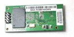
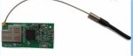
The TLG10UA03 is slightly smaller, comes with an external antenna to provide longer range, and has a simple 4-pin connection on .1" pitch header pins (4 other pins are optional).

The setup is simple. I provided it with 3.3 volts and 0V from a usb-serial dongle. After a minute, I searched for its wifi AP, connected to it, went in the browser to the IP it gave, signed in, and changed the settings so that it had an IP on my network, made it an "STA" mode connection (instead of AP), and gave it the SSID of my network AP. I made it a server and set the baud rate at 19200, the same as I had used on the RM04, and set the port at 8110. I rebooted it, and was able to reconnect over wifi to the new IP.

To test the module, I unplugged the RM04, provided my breadboard with 3.3 volts instead of 5V, and made the four connections to the TLG10UA03, using the same RX and TX pins as I had for the RM04. Provided power, waited for the wifi connection to be made, and then in the browser went to new IP with the same request I had used for the picaxe-supplied web page show in the previous thread: http://192.168.1.110:8110/temp.

This worked in IE, Opera, Chrome, Safari, and FireFox.

Documentation for the TLG10UA03 is here:
http://www.elechouse.com/elechouse/images/product/UART WiFi Transparent Module/User Manual-03_ENGLISH.pdf

The unit is available on Aliexpress for (as of this writing) $13.10 each for two:
http://www.aliexpress.com/item/2pcs-lot-2-4G-Wireless-WIFI-Module-TLG10UA03-Embedded-Uart-Wifi-Module-EEE802-11b-Antenna/1445140947.html

Of course, the picaxe doesn't have to be a web server--it can respond to serial input and provide serial output--all over the net via wifi.
 

Attachments

matherp

Senior Member
Hi Ibenson

I'm very interested in your experiences with this module. Have you got some sample code you could post using this module with the picaxe acting as a simple web server able to display the state of one or more inputs and modify an output?

There is a very good thread on using a WIZ110SR to do this
http://www.picaxeforum.co.uk/showthread.php?22755-Wiznet-WIZ110SR&highlight=web+server

The issue resolved there was that the WIZ110SR needed a timeout setting for the connection in order to get the web page to display. Unfortunately I had bought a different serial to IP module which didn't support the timeout so ended up only able to use telnet.

I would like to re-engineer my solution using wireless but obviously don't want to hit the same issue again.

Thanks

Peter
 

lbenson

Senior Member
Post 14 in the first link in original post shows a simple example. There is no difference in the code for this module. I have found that for both the TLG10UA03 and the HLK-RM04 it is necessary to put a pull-up on the tx line from the picaxe to eliminate garbage on the receiving end. I used 10K. Serial from the picaxe is in "T" mode, so the line idles high.

There may be timeout issues if the "Content Length" is not specified.
 

matherp

Senior Member
Well the units arrived but not the same version as you have and with different (c..p) firmware.

They do work but don't support any security except WEP and even that I haven't managed to get working. What is worse is that it appears impossible to get them into command mode on the serial port so I can't reset them in any way.

For anyone looking to use these modules, make sure you get the ones like Ibenson's picture
 

matherp

Senior Member
I'm really pleased with the easy way the TLG10UA03 can be interfaced and have been spending time developing a small but flexible PCB to allow simple deployment of remote applications. I've posted some details in http://www.picaxeforum.co.uk/showthread.php?25330-Wireless-Remote-Monitor-and-Controller&p=256659&posted=1#post256659
One of my recent projects has been to build a 3D printer (Prusa Mendel V2) and this is great for creating custom enclosures for picaxe projects. I've included a picture in the referenced post.
Thanks again to Ibenson for finding and cracking the use of this great little wifi module.

If you want to have a look at the system live you can try http://matherp.dyndns.org:50000
I'll try and leave it up over the next few days. You can press the buttons without fear of anything bad happening :)
 
Last edited:

D n T

Senior Member
Ibenson,
Just a small query, I have a remote controlled robot but the concrete walls of the facility don't agree with the 433mhz radio connection.
We have wifi through out the facility and it work well.
Could I use two of these to facilitate remote control of my robot?
 

lbenson

Senior Member
I can't say for certain, but if wifi works well then I would think that the TLG10UA03 would.
 

Hooter

Senior Member
Mr Benson - I need help - I'm not the only one to have said that.
I have purchased the TLG10UA03 and have been unable to communicate with it.
I have applied 3.3vdc to the device and can connect to it via my PC and android phone - but that is where it ends.
I am unable to browse to it to change any of the parameters. Is there a default IP address for the module?.
There is none suggested in the manual.
Could you please elaborate on the following statement - "After a minute, I searched for its wifi AP,
connected to it, went in the browser to the IP it gave, signed in,
and changed the settings so that it had an IP on my network,
made it an "STA" mode connection (instead of AP), and gave it the SSID of my network AP".
Any suggestions would be appreciated.
Hooter
 

lbenson

Senior Member
Sorry for your problems, Hooter.

I have gotten 6 of these TLG10UA03 devices. 4 of them worked as in the description you quoted, one I could connect to via serial but could not modify or reset, and one seems entirely dead. Unfortunately, for the two which don't work, I didn't check them until after the time period for returns or rejections had occurred.

For the ones which worked, a minute or so after I applied the 3.3vDC, I could look at wifi APs, see the device (don't remember the name, but fairly self-evident), and connect to it (password 000000). Then you can configure. I managed at one point to mess things up and did the "reset to defaults" connection and connected to the AP again.

You can also connect via serial using, for example, putty. Check the manual for the default baud rate, perhaps 9600. Copy "+++" (without the quote marks) and paste it into the terminal. Don't type it--you probably can't type fast enough to fit the timing. You should then get an "+OK" prompt and can type the commands as shown in the manual, especially "AT+RSTF" for factory reset and "AT+Z" for device reset.

Here are my cryptic notes:
Code:
with TLG10UA03, at 9600, escape string of "+++" gets "+OK" response; 
TLG10UA03 AT+RSTF ->factory; AT+Z reset; AT+PMTF save to flash; AT+QVER -> version AT+SSID
configured TLG10UA03 192.168.1.111 eh111 19200, port 8111; echo Hello | nc 192.168.1.111 8111 OK
TLG10UA03 AT+SSID=Omnibus9 AT+WJOIN AT+WSCAN AT+NIP
The configuration software, UART-WIFI, is available somewhere on the site, http://www.elechouse.com, but my notes don't tell me where. It did not help me for the 2 devices which I could not connect to by wifi.

I went back and forth a half dozen times by email with customer support--the person who wrote the English manual--but he wasn't a hardware guy and could never tell me if what I was doing to set it up via serial was correct, or what the right steps were. Good luck.

I have found that the devices work reliably once configured.
 

Hooter

Senior Member
Mr Benson - Thanks for the reply. I have finally got it sorted. I happened (just a guess) to use the PC's default gateway as the IP address to use in the browser which then took me to the log in menu. User name was admin and password was 000000 as you said.
I then carried out the same procedure with my second module and it worked first time.
I'm not sure if that is the proper method for everyone - but it worked for me.
Thanks again.
 

matherp

Senior Member
To use the UART-WIFI configuration software reliably I found the following works:

Connect to the device using one of the basic serial /usb adapters. Use an external 3.3V supply as the one on the adapter may not be powerful enough reliably to power the wifi board - just connect RX, TX and GND from the adapter and GND and 3.3V from the external supply.

Then run realterm and connect to the device (may be 9600 or 115200 baud). Use the send function to send +++ (no cr or lf) and you should get back the OK message
Then close the port on realterm and run UART-WIFI. Check the port number and baud rate are correct and then search for devices it should then find it OK and you can use it to configure the wifi-uart.

If you have the smaller version of the UART (blue PCB) rather than the bigger one (Green PCB) then its own configuration web page will not allow you to select any encryption other than none, WEP64, or WEP128. However, using the UART-WIFI software you can also set WPA etc.
 
Last edited:

PhilHornby

Senior Member
Uart-wifi

Then run realterm and connect to the device (may be 9600 or 115200 baud). Use the send function to send +++ (no cr or lf) and you should get back the OK message
Then close the port on realterm and run UART-WIFI.

There's a 'button' in UART-WIFI confusingly labelled "EXIT" under the heading "Transparent Transmission" that performs this function.


I've been playing around with the same version of the module that you used in your project and noticed that it's actually labelled TLN13UA06, which seems to be some sort of clone of the TLG10UA03, (as described on this site).

I'd be interested to know if the real TLG10UA03 has the same RTS/CTS bug that I have noted in the TLN13UA06 - namely that RTS is actually indicating the state of the Network link, and CTS works ... but is inverted.
 

lbenson

Senior Member
Yes it is the TLN13UA06 that I have--I hadn't noticed that tiny label.

RTS indicating network link could be useful.
 

PhilHornby

Senior Member
Tln13ua06

Actually, maybe I was being unkind, describing it as a 'clone'

Poking around the web I found what may be the manufacturer's site - it's all in Chinese. See: http://translate.google.co.uk/translate?hl=en&sl=zh-CN&u=http://www.wifitop1.com/product-3.html

There is a (Chinese) manual there for the TLN13UA06 - which is dated August 2013, so the TLN13UA06 might actually be a replacement for the TLG10UA03.

RTS indicating network link could be useful.
Yes, I suppose it could. That manual also describes the RTS/CTS implementation. Apparently they intended CTS to be active LOW (which I still think is odd!). RTS appears to be dual purpose:-

Translated Text said:
.3.2.2 hardware flow control mechanism

In the transparent transmission mode, the module supports hardware flow control serial transmission mode provides standard RTS / CTS signals, strongly recommended to use

Enable hardware flow control when carrying large amounts of data users, so as to fully ensure reliable data transmission. For flow control function is not required Applications, users simply RTS / CTS pin floating can.

Based on RTS / CTS hardware flow control using the mechanism is as follows:

◇ RTS: module receives the enable signal, active low, when the following conditions are satisfied, RTS signal is active

♦ conditions one: Wi-Fi is connected

♦ The second condition: UART receive buffer data length is less than 3/4 full

◇ CTS: host receives the enable signal, active low, the module detects stop immediately sent to the serial number of the CTS signal is invalid According until CTS becomes effective
 

PhilHornby

Senior Member
Power requirements...

Has anyone else noticed the slightly strange minimum voltage required by this unit? (Specifically, the TLN13UA06 variant).

The manual says it operates from 3.3±0.3 V and draws 300mA (typical).

Mine had been operating (extremely reliably), with power supplied by a LM2596-ADJ module (cheapo from eBay), while connected to a PicAxe which itself was running from 5V. I'd completely forgotten to do any sort of level-shifting, so the TLN13UA06 had been subject to about 4V on its RXD pin, but it seems to have survived unscathed (and it spent several weeks operating like this).

However, when I dismantled it all and re-configured it elsewhere, it suddenly stopped working. I realised that the main change, was the power supply to the TLN13UA06, which was now from the 3.3V line of an old PC PSU. According to my (un-calibrated) multimeter, this was supplying about 3.2V (i.e. well within spec.), whereas I'd set the LM2596-ADJ to more like 3.6V.

With a 3.6V supply, the RTS line goes high about 1.5 secs after applying power, and the wi-fi connects about 7.5 secs later (at which point RTS goes low again). Current drain is approximately 130mA throughout the process. When connected to the PC PSU, the RTS line 'pulses' in time with the green led on the module - and it never connects. If I adjust the LM2596-ADJ o/p down to 3.2V, it gives the same symptoms - so it appears to be the actual voltage that is the issue.


This behaviour seems rather peculiar to my (hobbyist) eyes. I was just wondering ... given the unit's ability to survive 4V on RXD - could this possibly be designed to run on 5V, rather than 3.3V? I've not dared try the experiment - since it will take a month for a replacement to arrive...

(I did try running it from the 3.3V line of a USB-Serial interface - and destroyed that) :mad:
 

srnet

Senior Member
Has anyone else noticed the slightly strange minimum voltage required by this unit? (Specifically, the TLN13UA06 variant).

The manual says it operates from 3.3±0.3 V and draws 300mA (typical).
So the device has an operating range of 3.0V to 3.6V ?

Nothing at all strange about that, fairly common on modern devices.

Difficult to predict what happens if you exceed the limits;

"TLN13UA06 had been subject to about 4V on its RXD pin, but it seems to have survived unscathed"

So you exceeded the limits (on the RXD pin) and you say it does not now operate correctly ?
 
Last edited:

PhilHornby

Senior Member
So the device has an operating range of 3.0V to 3.6V ?

Nothing at all strange about that, fairly common on modern devices.
Except that my particular example has an operating range of about 3.5 to 3.6 V. It definitely does not work over the quoted 3.0 to 3.6V range.

"TLN13UA06 had been subject to about 4V on its RXD pin, but it seems to have survived unscathed"

So you exceeded the limits (on the RXD pin) and you say it does not now operate correctly ?
If I put it back to its previous configuration - i.e. being fed with 3.5~3.6V - and still talking to the 5V powered Picaxe - it works fine. If I lower the supply voltage below about 3.5V (with or without the Picaxe in circuit), it does not work.
 

matherp

Senior Member
Put a 10uF tantalum across the pins of the wifi-uart and you may find the supply requirement changes. Also make sure there are no voltage losses on the wires to the uart. These things are pretty juicy and the supply requirement is intermittent.
 

PhilHornby

Senior Member
Max. current requirement.

Also make sure there are no voltage losses on the wires to the uart. These things are pretty juicy and the supply requirement is intermittent.
I think you're right.

I measured the voltage from the TLN13UA06's GND pin to what I considered to be ground - and to my surprise, it wasn't 0V. It wasn't constant either; it was fluctuating by a good few tenths of a volt. Then I noticed that the jumper that connected it to the breadboard was a good deal thinner than all the others in my collection. Swapping this wire radically altered the power requirements - it will now work down to about 3.1V (and so will run from the nominal 3.3V o/p of my PC PSU - which actually gives about 3.2V).

I set about finding out what the peak current requirements might be, by connecting an ammeter in series with the supply. This particular meter has a 'Max Hold' function, though I don't know how often it samples the current. In an unusually cautious move (for me!), I tried the 10A range first and got a max. reading of 0.14A. However, with the meter on its 200mA range, the TLN13UA06 would not connect to the wi-fi - even with a 3.6V supply. (It was back to pulsing the RTS line again). I tried doubling-up all my test leads, but to no avail. With the meter shorted out, it would connect, at which point I could remove the short and it would stay connected. The Max. current I recorded now was 145mA - so the same as before.

To my mind, this does seem to indicate some large peak in demand. It's not just at power-up time either; I can reproduce the same issues by rebooting the Access Point to which it's connected (the TLN13UA06 is in 'STA' mode).
 

PhilHornby

Senior Member
3.3V supply from USB to RS232C convertor

I have used 3V3 from a usb/serial module to power both picaxe and TLG10UA03 without problem.
The datasheet for the Prolific PL2303 module that I blew up doesn't say how much current the 3.3V line can supply. I've scoured the web, but haven't found any further information.

I've just bought some replacement modules that use the FTDI FT232RL; that IC's datasheet says that only 50mA is available for external logic...
 

hippy

Technical Support
Staff member
The amount of current which can be drawn from a USB-to-serial module invariably depends on how it is designed and the chips used.

If using an on-chip regulator then it likely only allows a few to tens of millamps to be drawn. If using an off-chip regulator then it could be up to 100mA or more. If delivering 5V direct from the USB port it will be whatever the USB port provides ( likely 100mA but can be higher ) less whatever the chip uses.
 

Pongo

Senior Member
I see there are now easy to connect HLK-RM04 boards on ebay, and as I read the original lbenson HLK-RM04 thread the only real downside to that device was the unfriendly header dimension. So is there any reason to choose the TLN13UA06/TLG10UA03 over the HLK-RM04? My interest is in a serial connection, picaxe serial -> wifi -> PC
 

lbenson

Senior Member
Either the TLN13UA06/TLG10UA03 or HLK-RM04 with expander board would work well. The HLK-RM04 board allows for wired connection as well as wireless. I have an HLK-RM04 like the one you linked to on ebay, but haven't used it yet. The HLK-RM04 board also allows you to install openWrt and toggle bits (but I haven't tried that).
 

Pongo

Senior Member
Thanks, I'll get the HLK-RM04 board. I've been using the serial to wired ethernet boards but thought I would give wifi a try for a solar powered instrument.

Edit: Aha, now I see that's most likely the HLK-RM04 "test board" that you referred to.
 
Last edited:
Top