Advice needed: Water Treatment Monitoring Project

jsmanson

Member
Hi gang! I am a beginner experimenter with the picaxe system. I am doing some conceptual design to build a controller/monitor, preferably using either picaxes, or possibly also using a data acquisition device I bought a while back (DLP deisgns I/O20 usb data acquisition module) for a small water treatment system for my rural property serviced by a couple of low yield brackish water wells. I will get to my question in due course, but I thought I would outline the project first:

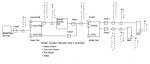
The water treatment system comprises of two low volume DC submersible pumps (variable speed 12-30 volt) with well water level transducers (4-20ma output), which pump into a 'small' tank, which is then re-pumped through a water softener, and optionally (depending on salinity readings of the raw water) through a reverse osmosis unit, into a larger 'processed water' tank which stores the processed water, which is pumped again on demand to the house. So I have two well pumps, two centrifugal pumps to pull water from the tanks, and the RO unit has it's own pump. All of this located in a secure shed behind the house with power.

I have the system up an running now using float switches in the tanks to tell the well pumps and the centrifugal pumps and the RO unit when to turn on (I currently manually switch between each well depending on water levels in the wells). The RO unit also has a nice little 'lockout' switch which will shut down the unit based on the state of a dry contact switch...

So..... what I want to do is this, using electronics:

1. Monitor water consumption from each well, as well as the water being processed through the RO unit (assuming it won't always have to run), and final water use into the home. This can be done using the little 3/4 inch dia hall effect sensors which you can get on ebay - this one gives 330 pulses per liter:

http://www.ebay.com/itm/G3-4-Water-Flow-Hall-Sensor-Switch-Flow-Meter-Flowmeter-Counter-DC-5V-24V-/171040909037?pt=LH_DefaultDomain_0&hash=item27d2d526ed

2. Monitor the salinity of the raw water before it hits the RO unit (I have two 4-20ma salinity sensors installed for this purpose, and I purchased a two sensor controller that displays the salinity and also provides an external voltage that can be used to 'read' the salinity value of each sensor). OK, so if the raw salinity is less than, say 200ppm, the 'computer' will activate a bypass solenoid that will allow the water to bypass the RO unit. When the water bypasses, the RO will sense the low inlet pressure and will automatically shut down.

3. If the RO unit is on, and the RO output salinity is over, say 300ppm, the RO unit should be shut down by the 'computer' (RO filters are done and need replacing).

4. If the water level in the well being pumped is too low, it will shut down that pump, and perhaps try the other well. Will prevent dry pumping...

So those are the 4 tasks I'd like the 'computer' to do. For flow monitoring, probably just converting the pulse data into actual flow, displaying instantaneous flow on an lcd, and storing the historical data to a USB flash drive would be the way to go. Same idea for the salinity readings, read the two voltages, and use the Digital out's on a picaxe to drive relays to bypass the RO or tell the RO to shut down. Well levels can also be monitored (4-20ma : ADC voltage in), displayed on an LCD, and recorded along with the flows.

So.... On to my question. Or questions.... I know that the picaxes are capable of doing all of these things, but I see this as perhaps asking to much for one picaxe to do on it's own, perhaps I need a picaxe or two to process the flow readings and record flow data, and another one to monitor well levels, and another one to turn the relay switches on/off and drive the lcd displays. If this is the best configuration, I could use some advice on how best to network the various picaxes effectively.

Or, alternatively, I could write a windows program to do the monitoring etc on a laptop that I would keep on at all times, and use the data acquisition module I mentioned above to interface to the various parts, although I might still need picaxes to read the pulsed flow data and convert that to an input that can be read by the windows program interface...

My idea at this point is to start small, and get flow and well level recording picaxes up and running and displaying and recording this data first, and go from there. Any comments from the picaxe wizards on my approach? Is this doable? I might also want to network the stuff back to the house - I have a cat 5 cable in the ground for that purpose, but that would be version 2 lol!!

John
 

lbenson

Senior Member
Looks doable--but advanced. What's the count of your inputs and outputs? I suspect a 20X2 would have enough I/O, but you might want to use a 28X2 for the additional program capacity.

Instead of an "always on" computer, you might consider running a picaxe-based web page, as shown here (with wifi): http://www.picaxeforum.co.uk/showthread.php?24691-picaxe-to-net-with-wifi-to-serial-module-HLK-RM04

And here, with wired wiznet: http://www.picaxeforum.co.uk/showthread.php?23486-Automatic-Home-Humidistat

The first link used a hard-to-hook-up wifi-to-serial module, the HLK-RM04. I just received today what seems to be a similar but more picaxe-able module, the TLG10UA03--I'll write it up when I have tested it. Both of these modules are under $20, so very affordable for a project of your scope.

You would need to be prepared to write a good bit of code.
 

SAborn

Senior Member
Not exactly a picaxe addition, but a suggestion.

An option you might like to try along with the RO unit is a condensation filter, its basically a sheet of dark tinted glass with a clear glass sheet over the top, all sealed in a box, a trickle bore water flows across the dark glass and returned back down the bore, while sunlight/heat causes some water to condense on the clear glass which is mounted on a slight slope, the condensation runs down the clear glass and into the tank. (fresh water)

Its not a fast system but it works well for little cost, and i know of others using it, the only problem i see is Canada has freezing temps.
 

Roman505

Member
As a side comment, doing it with a picaxe or even a few of them should be more reliable than doing it on any general purpose computer, simply on part and complexity counts, not to mention avoiding spinning disk.
 

manuka

Senior Member
jsmanson: Top marks on a lucid outline! At first pass I'd say you may want to also consider a Raspberry Pi. But where in Canada are you - freezing issues likely? What is this water for - utility or drinking? Are you allowed to -gasp!- collect rain water in your area? Stan.
 

jsmanson

Member
Thanks gang for your responses!

SABorn: The system is to provide us with about 100-150 gal of fresh domestic water for the house, so an RO unit is required for sure....

I am located on the west coast, I will have a bit of freezing our here to contend with, but's it's fairly minor, the shed is half underground so it apparently never freezes in there. Might need a bit of heat tape for the larger tank outside for the drain line which always has water in it. Roman, I agree that picaxes running 24/7 would likely be more reliable than any kind of computer, so I am leaning that way, and I like the challenge of putting the picaxes together, so I'll try it that way. I've got a 40x2 part around from another project, so I might start with that one as it has the most i/o's, unless others think that one of the multitasking ones would be better. thinking of that...

Multitasking. So one of the chores that will need to be done is measuring water flows from 2 or 3 different flow sensors. Looks like a "count" command will be best for this, and I had toyed with multitasking a picaxe to continuously measure these flows while the code is running through other tasks, but I see in the manual that they don't recommend pulse in/out commands using multi-tasking as the cpu is'nt 100% dedicated to the task at hand when the code is running. As I don't need to have 100% time based flow measurement, I can live with, say a 1 second flow sample taken every minute or so, I am thinking about designing the thing to run as a sequentially run (i.e. non-multi-tasking) program, i.e.

start01:
1. Monitor and record flow readings from each sensor, say 1 sec per sensor;
2. Monitor and record well levels (that's just a voltage measurement)
3. determine which well pump is currently in operation (if any);
4. If well pump "1" is operating, determine if there is sufficient water in that well...
if not, turn off that pump, set well No 1 low level alarm, increment a well failure variable by one, turn on well pump "2";
if OK, then no action;
5. Repeat 4. for each of the other pumps, but if the well failure variable equals the number of wells, set an "All Wells are dry" alarm, and shut down all well pumps;
5. Determine if Reverse Osmosis (RO) unit is running if it is........
check input salinity....
If < 200, water doesn't need to go through RO unit, activate bypass Solenoid (RO will shut down automatically) else...
check RO output salinity.....
If output salinity > 200, RO unit is faulty, shut down RO unit, activate RO treatment failure alarm, else
Carry on.
If RO unit is off, carry on.
6. Shove data out to the displays (flows, alarm LEDs, etc)
7. lbenson's idea: Push the data up to a web site using wireless or wired connection to the NET (I like this idea!)
return to start01:

Please comment gang on my flowchart here, if you think I am missing anything. One of the great things about this project is that it can be expanded - the RO unit for example needs to be manually flushed out every couple of weeks, and that would be easy to automate, could do it based on flows through the RO unit, and another solenoid valve...

I am also toying with adding a rainwater system to the mix, but that will be considered only if the well capacity proves to be a problem next summer.....

And thanks in advance for all of your input!
 
Last edited:

lbenson

Senior Member
I'd been thinking about your idea. Because counting pulses from your flow monitors with as many other I/Os as you have would be a challenge, I looked into how it might work to have a separate picaxe do the counting.

It appears to me that an 08M2 can count on 4 input pins, and if any count exceeds a threshold, it initiates a 2-wire conversation with the master to notify it. The conversation is a Request-to-Send and Clear-to-Send handshake, with the RTS line then used to transmit a byte using serout telling which pin the threshold was passed on. The master can delay responding without losing counts.

Here's the picaxe program:
Code:
'08pulsecounter.BAS counts pulses on 4 pins; when count above
'  threshold, raise pin0; when pin1 high, lower pin0 and send
'  id of pin on pin0 with serout
#picaxe 08M2 
#no_data

symbol reportPin = 0
symbol CTSPin = pin1
symbol port1Pin = pin2
symbol port2Pin = pin3
symbol port3Pin = pin4
symbol port4Pin = pin5

symbol baudrate=N19200_16
symbol threshold=4 ' 330 pulses per litre

symbol flagByte=b0    ' reserved for bit values
symbol lastPort1=bit0 ' last value of port1 (0 or 1)
symbol lastPort2=bit1
symbol lastPort3=bit2
symbol lastPort4=bit3
symbol port1Ready=bit4 ' ready for over-threshold signal
symbol port2Ready=bit5
symbol port3Ready=bit6
symbol port4Ready=bit7

symbol flagByte2=b1    ' reserved for bit values
symbol RTSFlag=bit8

symbol readyFlag = b2
symbol reportByte = b3
symbol port1Cnt = w2
symbol port2Cnt = w3
symbol port3Cnt = w4
symbol port4Cnt = w5

' s_w1 through s_w6 available as words
'symbol port1Cnt = s_w1
'symbol port2Cnt = s_w2
'symbol port3Cnt = s_w3
'symbol port4Cnt = s_w4

SETFREQ M16

start:
  pause 2000
  disconnect
  
sertxd ("08pulsecounter ",13,10)
main:
  do
    if port1Pin <> lastPort1 then ' change in value
      lastPort1 = port1Pin
      if lastPort1 = 1 then ' change was from low to high--new pulse
        inc port1Cnt
        if port1Cnt > threshold then
          reportByte = "1" ' over threshold on 1st port
          port1Ready = 1
          RTSFlag = 1      ' we are requesting to send
        endif
      endif
    endif

    if port2Pin <> lastPort2 then ' change in value
      lastPort2 = port2Pin
      if lastPort2 = 1 then ' change was from low to high--new pulse
        inc port2Cnt
        if port2Cnt > threshold then
          reportByte = "2" ' over threshold on 1st port
          port2Ready = 1
          RTSFlag = 1      ' we are requesting to send
        endif
      endif
    endif

    if port3Pin <> lastPort3 then ' change in value
      lastPort3 = port3Pin
      if lastPort3 = 1 then ' change was from low to high--new pulse
        inc port3Cnt
        if port3Cnt > threshold then
          reportByte = "3" ' over threshold on 1st port
          port3Ready = 1
          RTSFlag = 1      ' we are requesting to send
        endif
      endif
    endif

    if port4Pin <> lastPort4 then ' change in value
      lastPort4 = port4Pin
      if lastPort4 = 1 then ' change was from low to high--new pulse
        inc port4Cnt
        if port4Cnt > threshold then
          reportByte = "4" ' over threshold on 1st port
          port4Ready = 1
          RTSFlag = 1      ' we are requesting to send
        endif
      endif
    endif

    
    if RTSFlag = 1 then ' we are requesting to send
      if CTSPin = 1 then ' client is listening
        low reportPin
        pause 1
        serout reportPin,baudrate,(reportByte)
        low reportPin
        select reportByte
          case "1"
            port1Cnt = port1Cnt - threshold
            port1Ready = 0
          case "2"
            port2Cnt = port2Cnt - threshold
            port2Ready = 0
          case "3"
            port3Cnt = port3Cnt - threshold
            port3Ready = 0
          case "4"
            port4Cnt = port4Cnt - threshold
            port4Ready = 0
        end select
        reportByte = 0
      endif
    endif
    
' check for additional over-threshold conditions
    readyFlag = flagByte & %11110000
    if readyFlag > 0 then 
      readyFlag = flagByte & %00010000
      if readyFlag > 0 then 
        reportByte = "1"
        high reportPin
      endif
      readyFlag = flagByte & %00100000
      if readyFlag > 0 then 
        reportByte = "2"
        high reportPin
      endif
      readyFlag = flagByte & %01000000
      if readyFlag > 0 then 
        reportByte = "3"
        high reportPin
      endif
      readyFlag = flagByte & %10000000
      if readyFlag > 0 then 
        reportByte = "4"
        high reportPin
      endif
    endif
  loop
The monitors you linked to have a capacity of 60 litres per minute, but I suspect you won't approach that. I would run the picaxe at 32mHz. At that rate I don't think it would miss more than a very small fraction of the 330 pulses per litre--less than the error range of the device.

The program doesn't use the COUNT command--it just cycles rapidly checking to see if an input pin has gone high where it was previously low. The counts are on pins 2, 3, 4, and 5. RTS and serout are on pin 0, and CTS from the master on pin 1. Counts continue above the threshold and after RTS has been asserted.

The master should see RTS and respond when it is convenient by bringing CTS high and immediately doing a SERIN for one byte, which will be "1", "2", "3", or "4" depending on which line passed the threshold. I set a threshold of 1 litre--330 pulses. CTS must be de-asserted once the byte has been read. If another input has passed the threshold in the meantime, the 08M2 will immediately initiate another handshake and will continue counting until the master is ready again.

I tested this in the simulator, but wouldn't guarantee it, of course.
 

jsmanson

Member
LBenson: Great, I really appreciate the help with this - you are right, I think 5-7 gpm is about the maximum flow I will see through the system, and my particular brand of flow meter may have a different count per liter, but that's all workable. Not sure I have an 08M2 around here, but I know I have a bigger part that should work fine, perhaps a bit of overkill. And the thing isn't operating in multitasking mode right? I am assuming that the main picaxe will have to do the math using the current time to figure out the flow rate based on the time spacing between the 'interrupts'... Right? Or would it be easier to program the remote picaxe to calculate the instantaneous flow rates, and the main picaxe could request the current flow numbers when it cycles around as per my flow chart.... Perhaps using i2c or something like that?? Thanks for your time on this!!

John
 

SAborn

Senior Member
You could just use the remote picaxe to read flow and send it to the master via hardware serial, that way it will be received in the background and the master just needs to read the variable for the flowrate.

I done a similar thing with an aneomometer as it speeded up the master data processing time.
 

lbenson

Senior Member
The 4-channel pulse counter program I posted should work fine on a 20m2, though it would be overkill.

Regarding having the pulse counting front end do further processing to determine flow counts, it doesn't seem to me to be a good idea. If you have a maximum of 7 gallons per minute, let's say that's about 24 litres per minute. That's 2.5 seconds per litre, and at 330 pulses per litre, 132 pulses per second, times 4 possible sources of pulses, some of them likely to be near simultaneous. I think the program I posted could keep up with that, missing very few pulses, but if it tried to do anything else, it might miss some.

On the other hand, the master would at the highest rate receive only about a pulse or two every second--plenty of time for a fast picaxe to process that and a lot of other I/O at the same time.
 

jsmanson

Member
Yup, sounds good, I will get the 40x2 to do the math. Would it be worth throwing a math co pro off the main picaxe as well, or just stick to integer math? I ordered a wiz net from spark fun in the US to connect the main picaxe to the net, I have to add writing a web server to the to-do list. I have started at johnmanson.ca\water, but i will need to study how to do that.....

Thanks for all of your great suggestions to date!

John
 

lbenson

Senior Member
>Would it be worth throwing a math co pro off the main picaxe as well

What math are you expecting to have to do? Users have posted code to enhance the native abilities of the picaxe. A lot can be done with picaxe integer math if you are careful about overflows and underflows.

I looked at the template you have set up at johnmanson.ca\water. I don't think people were talking about a www hosted web server, but a local one--either based on a PC or a little Linux device like the routers which run openWrt, or even a server entirely hosted on a picaxe. Note that such a server could be made available to the internet, or just to your local network.
 

jsmanson

Member
Turns out a already have a website set up, I thought it would be just as easy to stick the stuff up there, I can monitor when I'm away from the house without any security issues. I haven't decided if I want to be able to talk back to the picaxe from 'outside', if I do, I guess I will have to set up my router firewall to allow this. My router is a D-link WR-632 running DD-WRT third party firmware, I suppose that might be an option as well...
 

lbenson

Senior Member
This project interested me because it looked like a moderately complex task which I could use as an example in a model I've wanted to build--hardware and software. I hope you don't mind if I use a simplified version.

I have a couple of questions. In what format do the salinity sensors deliver their results?

Have you figured out what I/Os you're going to need? I see at least 15, including the 4 pulse counters for the water flow.
 

jsmanson

Member
Sorry, I've been away from the project for a while..... and waiting for more parts to arrive :)

OK, I have decided to do all the measurements with picaxes, including 1 or 2 to continuously monitor flow - they will communicate with a main picaxe that will be programmed to make the ongoing operating 'decisions' i.e. when to turn pumps and things on and off. Flow data and current operating parameters will be transmitted from the main picaxe through a wiznet 100SR module over hardwired Ethernet to the house, where I am going to run a raspberry Pi webserver, running MySQL or something like that to log the data into a database, and serve up the info on a locally hosted website, or I might just expose the database over the network and look at it with a computer.

So lots of things to do, I will start with programming the 'flow' picaxes, making sure they accurately measure flow, then I will tackle the main picaxe, checking that it is seeing all inputs, and taking correct actions based on the inputs.

lbenson, the salinity probes work through a 'controller', I got one used for cheap (Rosemount Analytics Solu Comp II Controller) which seems to be malfunctioning at the moment (hopefully a cold solder joint problem or something like that), which when working properly, will put out separate 4-20ma signals which I will convert to a 0-5 volt output for the picaxe.

Then I'll start playing with the Ethernet connection, and the raspberry pi, fascinating little toy!

Oh, I will start working on those I/O's as well, the main picaxe will be a 40x2, so I should have enough with that thing....

John
 
Last edited:

jsmanson

Member
Hi there, firstly, I very much appreciate the work you (L Benson) did here in writing the entire program for monitoring the flow sensors. I am back moving forward with the project, I have decided to use a 20M2 for the flow sensor processor (can it maybe handle 6 sensors rather than 4? running at 16mhz I presume...). The main picaxe will be an older 40X2, it has enough i/o's to do all the things I need to do plus some spare capacity, I will run it at 16 mhz as well. I have them set up together, with 2 OLED Axe27 boards hooked up to each processor for debugging and monitoring operations.

I used your code pretty much as you have it for the 20M2, but I am struggling a bit on getting communications working correctly between these two picaxes, as well as some struggles getting the 40x2 to talk properly to the wiznet110 board that's networking back to the home computer (will eventually be a raspberry Pi with a webserver ap running on it). I will get back to the wiznet problems once I have the two picaxes talking to each other....

So back to the two picaxes..... Looks like you suggested doing the serial comms at 19.2k baud, I see in the manual that 'they' don't recommend going over 4800 baud, so I may try it at the lower speed before going up to 19.2K. I took apart one of the flow sensors so I can 'spin' it manually, and the LCD shows the pulses being processed, and the trigger rountine works correctly (it shows the program moving to the serout command section of code, but the receiving 40X2 does not receive the data correctly... So one question on the handshake protocol you have developed... When the trigger is reached (i.e the RTSFlag = 1), shouldn't the 20M2 now set the report pin (pin 0) high, to signal to the 40X2 that data is ready for sending? Then, when the 40x2 is ready to receive it, it will respond by setting CTS high, which then triggers the transfer from the 20M2 using the RTS line. I will modify the code to set the report pin high in each of the 4 if statements, and see if that makes things work!

And another quick question, on the 40X2 and the wiznet... I have reserved the hserin and hserout pins for hardware serial comms between the net the the 40x2 through the wiznet, is this a better way to go than just using standard serial comms? The 40x2 is going to be running a half dozen routines in sequence, so I am thinking that a request coming in through HTTP can be shoved into the scratchpad automatically, and dealt with when the main code has finished being processed. And does anyone have any recommended comm speeds for taking to the wiznet? 19.2k will work there too, or is that too fast? Thanks again for your help gang!

Ah yes, one final comment.... On both the serial connections between the 40x2 and the 20M2 and the wiznet, do you need the resisters between these guys, or can you direct connect? I am connecting to the board contacts on the bottom of the wiznet (TTL?), not to the pins in the serial connector... and yes, I have 0V connecting all the gadgets :)

John
 
Last edited:

lbenson

Senior Member
I wrote a pulse-generating front end to the pulse-counting front end I had written previously, and have debugged it from generation through counting through reporting through receiving report--08M2->08M2->20M2.

Here is the pulse-counting code:
Code:
'08pulsecounter.BAS counts pulses on 4 pins; when count above
'  threshold, raise pin0; when pin1 high, lower pin0 and send
'  id of pin on pin0 with serout
#picaxe 08M2 
#no_data
#terminal 19200 'turn on terminal after program load
'#terminal 38200 'turn on terminal after program load

symbol reportPin = 0
symbol CTSPin = pin1
symbol port1Pin = pin2
symbol port2Pin = pin3
symbol port3Pin = pin4
symbol port4Pin = pin5

symbol baudrate=N19200_16
symbol threshold=4 ' 330 pulses per litre

symbol flagByte=b0    ' reserved for bit values
symbol lastPort1=bit0 ' last value of port1 (0 or 1)
symbol lastPort2=bit1
symbol lastPort3=bit2
symbol lastPort4=bit3
symbol port1Ready=bit4 ' ready for over-threshold signal
symbol port2Ready=bit5
symbol port3Ready=bit6
symbol port4Ready=bit7

symbol flagByte2=b1    ' reserved for bit values
symbol RTSFlag=bit8

symbol readyFlag = b2
symbol reportByte = b3
symbol port1Cnt = w2
symbol port2Cnt = w3
symbol port3Cnt = w4
symbol port4Cnt = w5

' s_w1 through s_w6 available as words
'symbol port1Cnt = s_w1
'symbol port2Cnt = s_w2
'symbol port3Cnt = s_w3
'symbol port4Cnt = s_w4

SETFREQ M16
'SETFREQ M32

start:
  pause 2000
  disconnect
  
sertxd ("08pulsecounter ",13,10)
main:
  do
    if port1Pin <> lastPort1 then ' change in value
      lastPort1 = port1Pin
      if lastPort1 = 1 then ' change was from low to high--new pulse
        inc port1Cnt
        if port1Cnt > threshold then
          reportByte = "1" ' over threshold on 1st port
          port1Ready = 1
          RTSFlag = 1      ' we are requesting to send
        endif
      endif
    endif

    if port2Pin <> lastPort2 then ' change in value
      lastPort2 = port2Pin
      if lastPort2 = 1 then ' change was from low to high--new pulse
        inc port2Cnt
        if port2Cnt > threshold then
          reportByte = "2" ' over threshold on 1st port
          port2Ready = 1
          RTSFlag = 1      ' we are requesting to send
        endif
      endif
    endif

    if port3Pin <> lastPort3 then ' change in value
      lastPort3 = port3Pin
      if lastPort3 = 1 then ' change was from low to high--new pulse
        inc port3Cnt
        if port3Cnt > threshold then
          reportByte = "3" ' over threshold on 1st port
          port3Ready = 1
          RTSFlag = 1      ' we are requesting to send
        endif
      endif
    endif

    if port4Pin <> lastPort4 then ' change in value
      lastPort4 = port4Pin
      if lastPort4 = 1 then ' change was from low to high--new pulse
        inc port4Cnt
        if port4Cnt > threshold then
          reportByte = "4" ' over threshold on 1st port
          port4Ready = 1
          RTSFlag = 1      ' we are requesting to send
        endif
      endif
    endif

    
    if RTSFlag = 1 then ' we are requesting to send
      if CTSPin = 1 then ' client is listening
        low reportPin
        pause 10
        serout reportPin,baudrate,(reportByte)
        low reportPin
        select reportByte
          case "1"
            port1Cnt = port1Cnt - threshold
            port1Ready = 0
          case "2"
            port2Cnt = port2Cnt - threshold
            port2Ready = 0
          case "3"
            port3Cnt = port3Cnt - threshold
            port3Ready = 0
          case "4"
            port4Cnt = port4Cnt - threshold
            port4Ready = 0
        end select
        reportByte = 0
      endif
    endif
    
' check for additional over-threshold conditions
    readyFlag = flagByte & %11110000
    if readyFlag > 0 then 
      readyFlag = flagByte & %00010000
      if readyFlag > 0 then 
        reportByte = "1"
        high reportPin
      endif
      readyFlag = flagByte & %00100000
      if readyFlag > 0 then 
        reportByte = "2"
        high reportPin
      endif
      readyFlag = flagByte & %01000000
      if readyFlag > 0 then 
        reportByte = "3"
        high reportPin
      endif
      readyFlag = flagByte & %10000000
      if readyFlag > 0 then 
        reportByte = "4"
        high reportPin
      endif
    endif
  loop
And the end-code (would be on your 40X2) which receives the per-litre notifications:
Code:
'20test2.bas miscellaneous testing
#picaxe 20M2 
#terminal 19200 'turn on terminal after program load
symbol RTSin=C.6
symbol RTSinPin=pinC.6
symbol CTSPin=C.7

symbol value=b25

pause 6000
setfreq m16
sertxd("20test2",13,10)
do
  if RTSinPin = 1 then ' litre message from pulse counter
    high CTSPIN
    serin RTSin,N19200_16,value
    low CTSPIN
    sertxd("sim cmd: ",#value," ",value,cr,lf)
    select value
      case "1"
    endselect
  endif
loop
I had no trouble with a baud rate of 19200 (which I used to get back quicker to the pulse counting). I just used bare wires from picaxe to picaxe, but it would be safer to have an in-line 1k resistor to guard against programming mishaps.
 

jsmanson

Member
Thanks again - Larry? Guessing an L name lol....

I will try your code direct tonight when I get back home, might be tomorrow night... I still see the need to set reportpin high in your 4 if statements that detect the initial threshold being met, if they are not there I guess the report pin going "high" be be picked up when you do your additional check after the rtspin = 1 if statement. I modified your code as below - please excuse the sloppiness etc... for the 20M2 and the 40x2. I think the baud problem may be related to the axe134y oled's, so for the time being I am running at 4 mhz. I had some problems with unconnected pins giving spurious flow counts, figured that one out, connected the unused pins to 0V and it's running properly from the 20M2 side..

I have been using those oled's partly because I wasn't sure how to setup the download cable and sertxt text back to the computer when programming two picaxes at the same time. I am presuming that you are using two separate download cable jacks, one for each picaxe, each one separately feeding the serin wire to it's picaxe, and connecting the two picaxe sertxt out wires together so both picaxes can talk to the computer when they are running? Otherwise, if you wire the sertxt's separately to each cable jack, you'll just get the sertxt messages for the picaxe that is currently connected to the computer when it is running, right?

John
 

Attachments

lbenson

Senior Member
"L" is for Lance

reportPin is not set high until after the comment, "' check for additional over-threshold conditions". That comment is misleading--it is for +any+ over-threshold conditions.

Debugging has become interesting with 3 picaxes. You can do two at a time by running PE5 and PE6 at the same time (no conflict, thanks, Rev-Ed). I've used my small auxiliary laptop, an eeePC, to run another instance of PE5 or 6. I've also used usb-to-serial modules running putty. The problem with those is that they use true ("T") rather than inverted ("N") logic, and in some cases the idle-high state causes the picaxes to be "phantom powered", which confused me for a while. I've just made up a logic inverter with two p2n2222 transistors so I can more conveniently use the usb-to-serial dongles for monitoring idle-low picaxe output. I also found that running an idle-high line into the picaxe through an inline 10K resistor prevented the phantom powering.

Another little connector I've made is 3 pins in and out with the 10K and 22K programming resistors in place--with that I can program on a breadboard without having the connector and resistors on the breadboard.
 
Last edited:

jsmanson

Member
Thanks Lance - it's all working now, but in order to get the correct info (reportpin value) from the 40x2 to the 20m2, I have to insert a setfreq m4 immediately before the serout, and serin commands in both picaxes, then I can go back to setfreq m16 after that, might be a limitation on the older 40x2 chip, it's one of the earlier ones. Also, interesting that I have the com5 virtual com port (axe0127 usb cable) on the PC set for 9600 baud, it doesn't seem to work above 4800 either, but again I can work around that, and thats just for testing anyways.... Now back to the rest of the project! - Cheers John Hope the weather is great back there!
 

lbenson

Senior Member
As I said, this project interested me, mainly because it offered a fairly complex monitoring and control problem on which I could test my idea about having a picaxe serve a complex web page wirelessly.

I've completed (for now) my interpretation of this problem, and documented my adventure here: http://www.picaxeforum.co.uk/showthread.php?25050-Picaxe-Web-Server-Water-System-Monitor-and-Controller

I don't claim that this is a solution to this particular problem, but it's close, and illustrates what can be done.
 

Attachments

jsmanson

Member
Lance, you have done an amazing piece of work here. I didn't really think that these little picaxes could handle serving up web pages, but you've certainly managed to do it! I will try now to implement what you have put together, with only a few changes....

1. I have a water softener in between the first tank and the RO unit. Every 3,000 gallons or so, it goes through a flush cycle, which needs 150 gallons to complete the cycle. I have managed to install a microswich on the unit which triggers when the flush cycle starts, so I was going to get the program to detect that condition, and then check the water levels in the first tank (it's only a 200 Gal tank) - if the water level drops below, say 50 gal, a solenoid will connect the main tank (finished water) outlet BACK to the first tank to ensure it doesn't run down to the point where the first tank pump will shut off, staving the water softener of water during it's cycle. It will also trigger a fault on the RO so it won't start up during the flush cycle, which might happen if I start emptying the second tank.

2. I don't really need a wireless connection for the server, I was going to use the wiznet110sr regular wired serial to TCPIP contraption to talk to the net.

Otherwsie I'm going to go with your setup Lance!

Thanks again, I got away from the project again, so I didn't se your work that you posted last Christmas until just now...

Hope the spring is coming your way, we had a very dry winter out west, finally got some rain and snow this last week, there was talk of a 20-50 year drought on winter precip, but it looks like it's turing around....

Cheers, I will let you know how I make out - I'll order the eeproms and other parts you added in....

John
 

lbenson

Senior Member
John,

Your additions make for a bit more complication, and make your choice of the 40X2 a good one. I've gone that route also for my next version of the html server, and am awaiting some PCBs I ordered from OSH Park. When they arrive and are tested, I'll post the Eagle files, which you might find of use. I also have some streamlining of my code after adaptation to the 40X2, and I'll post that when it's ready.

Wireless wasn't necessary--it just bugged me (and bugs me) that serial ethernet modules like the Wiznet 110sr cost twice what the TLG10UA03 wifi serial device does.

Not much sign of spring here in Nova Scotia, but I hope we've had the last of the -18C weather. And there's no lack of moisture--the Mersey river is running about a foot higher than normal, and a number of my favorite bird-attracting rocks are under water. Did see a gull swallow an eel that was longer than the gull, and couldn't have weighed much less, last week. And see eagles in a tree across the river almost daily.

Picaxe has made for a good wintertime project for me--I've been pounding away at various parts of a picaxe ecosystem nearly every day since early December.

Good luck with your ongoing project, and keep us posted.
 
Top