AS1115 Led Driver - I2C
- Thread starter NVHLVNOP
- Start date
The device uses I2c to communicate with a host. Perhaps if you better describe the trouble you are having and post the code you have tried, then folks will at least have a starting point.
Also when asking for help with a specific device it is good etiquette to post a link to the datasheet so that folks don't have to search for it. The less vague you are and the more information you provide, the better help you will receive.
The datasheet can be found here ======> AS1115 Datasheet
First Question: Do you have pullup resistors on the SDA,SCL, and IRQ lines? What size ? (See Figure 16 in the Datasheet)
You'll find it if you search AS1115 on digikey. I'll attempt to paste the data sheet here but not sure if it will work since I'm on my smartphone. http://www.ams.com/eng/content/download/18430/343782
As said, it would be helpful for you to post your programme/code so far.
It may just be a simple oversight that a second pair eyes can spot.
If you are new to I2C and it is a meaningless nightmare then be up-front and some kind soul may walk you through... or at least start you.
It may just be a simple oversight that a second pair eyes can spot.
If you are new to I2C and it is a meaningless nightmare then be up-front and some kind soul may walk you through... or at least start you.
Not on my pc now so I don't have the exact code available, but it is a simple loop that counts from 0 to 999 and sends the number to a 3 digit LED 7-segment display.
To send info to the chip I use:
i2cslave %00000000, i2cfast, i2cword
i2cwrite 0, (command byte, data byte, command byte, data byte, command byte, data byte)
I do not repeat the "i2cslave %00000000, i2cfast, i2cword" line between i2cwrite commands.
Yes, this is my 1st attempt at using I2C. I have 4k7 pull-ups on SCL and SDA lines.
Noted comment about etiquette posting datasheets. Will do so in the future.
The AS1115 appears to be quite a complicated device for a first foray into using I2C. It would be recommended to get your I2C working with an I2C EEPROM first to ensure that the hardware is correct. Also always start with I2CSLOW speed until things are working.
The device seems to use the 'command byte' as a location/register address so I2CBYTE would be the most appropriate setting for that. Each HI2COUT ( or I2CWRITE ) command should only have one command byte, sent as the location address byte.
The device appears to need configuring before it shows any data. Trying to find some existing code for the AS1115, even if not for a PICAXE, would probably be useful as a reference.
Thanks Hippy, so would you suggest something like:
i2cwrite command_byte, (data_byte)?
Or will the beginning address always be zero, i.e. i2cwrite 0, (......)
I used i2cword instead of i2c byte because Figure 22 in the datasheet shows the AS1115 Registers are 16 bits (1 command byte and 1 data byte). The same figure also shows that at the end of the data byte, there is an autoincrement of the memory word address. Let me know if I'm incorrect and should still try out i2cbyte again. I did start off with i2c byte and nothing happened so that's why it is currently set as i2cword.
Yes. It's not the easiest of datasheets to follow but it seems to me that the command byte is 8 bits and represents a location so the address mode should be I2CBYTE.Thanks Hippy, so would you suggest something like:
i2cwrite command_byte, (data_byte)?
Attached are C and Hex files for As1115 Driver for ARM. The C file should give good information on configuration
Attachments
-
8 KB Views: 32
-
3.7 KB Views: 22
I checked out the C and Hex files and got very lost, lol. I pretty much know only Picaxe Basic. I'll try i2cwrite command_byte, (data_byte) when I get home and see how it goes. Earlier, I did a continuity check as well as check for shorts in the hardware and everything turned out okay. I ruled that out, so now it seems the problem lies in the code. I'll post any successful results if I get them. And don't worry, I'll also post the unsuccessful ones along with more questions ")
I do not know about the AMS AS115 being noted on the PICAXE forum in the past but certainly there have been some references to the AMS AS11xx series. Here is one:
http://www.picaxeforum.co.uk/showthread.php?17086-PICAXE-28X2-and-AS1112-Led-Drivers&highlight=AS111*
http://www.picaxeforum.co.uk/showthread.php?17086-PICAXE-28X2-and-AS1112-Led-Drivers&highlight=AS111*
Last edited:
westaust55
Moderator
The AS1112 mentioned above by ValueAdd is an SPI interfaced chip.
The OP’s AS1115 is an i2c interface chip..
I note form the datsaaheet:
The C code posted by Goeytex at post 10 does not help in terms of setting a new slave address as it defines:
So they were leaving the slave address as %00000000
The OP’s AS1115 is an i2c interface chip..
I note form the datsaaheet:
And’The default slave address is factory-set to 0000000
Slave address %00000000 is a general call address for all i2c devices and is not supported by the PICAXE chips.If this feature is used, 2 of the 16 key readback nodes can be left open or shorted for self-addressing. This is done with KEYA together with SEGG and SEGF. This two nodes cannot be used for key-readback in this case. After startup all devices have the predefined address 0000000. A single command for self-addressing will update all connected AS1115.
The C code posted by Goeytex at post 10 does not help in terms of setting a new slave address as it defines:
#define AS1115_ADDRESS (0x00 << 1)
So they were leaving the slave address as %00000000
Last edited:
I read about the self addressing and didn't really get it. So there is no way to short pins and create an alternate address? Is it saying that changing the address has do be done thru commands, after first addressing the chip as 0000000? This could explain why I spent another 2 hours trying all options and still ended up unsuccessful.
See I told you I'd have more questions
They make the same chip with serial com rather than i2c. Perhaps I can try that one? Any other 64 led drivers you've used successfully? Something in the $5 range would be best.
See I told you I'd have more questions
They make the same chip with serial com rather than i2c. Perhaps I can try that one? Any other 64 led drivers you've used successfully? Something in the $5 range would be best.
Well, the obvious answer is max7219. Problem is if you pay $5 you will be getting a "fake". You might be lucky, like I was, and find it works fine. Or you might not be lucky.... Genuine max7219 cost in the $10-15 range. There was a thread on spotting the fakes, do a forum search for "fake". Max7219 has an SPI/serial type interface.Any other 64 led drivers you've used successfully? Something in the $5 range would be best.
Paul
westaust55
Moderator
How many digits are you wishing to display?
The SAA1064 is i2c and can drive 4 digits.
I have posted a "getting started" tutorial on this forum.
The PT6961 can drive 6-digits with up to 12-segments per digit/character. SPI interface.
I have done some work with this chip and a 6digit 12seg display but other than as part of 4-digit 7-seg displays they are seemingly scarce.
I got the impression from the word I quoted from the AS1115 Datasheet that an alternate address may be possible by connecting a keys an line to a couple of segment lines.
Same Austria Microsystems AS family - AS1107 - pin compatible (plus a bit more) as MAX7219 but a lot cheaper. Available in DIP and SOICAny other 64 led drivers you've used successfully? Something in the $5 range would be best.
I think it also says that this has to be done each time power is applied, ie not persistent. Very inconvenient!I got the impression from the word I quoted from the AS1115 Datasheet that an alternate address may be possible by connecting a keys an line to a couple of segment lines.
Not too inconvenient though. I did not study the datasheet in depth but it appears that a single command sent to all chips causes each to load their address from whatever external links have been made; then it's just a matter of using the right address for the right chip. If there's only one chip then no addressing configuration to be done - I think; Goeytex's useful code will help there.I think it also says that this has to be done each time power is applied, ie not persistent. Very inconvenient!
I would try to get writing and reading a digit register working first, not worry about anything else other than what is written can be read and is the same. That will allow the correct device address to be found.
Then it's just a question of converting the C code sequences into PICAXE code sequences then adjusting configuration values to how it's actually wanted to use the display.
It's a bit tricky because it's a 'black box', probably nothing will work until things are right, but methodically working through things should get it working.
westaust55
Moderator
But there is the problem as I mentioned earlier that the default slave address is the general call address $00 which PICAXE does not support.
Could it be possible to "bit-bang" that first command? All following comms between the 2 chips could use the updated address and the normal i2c commands.But there is the problem as I mentioned earlier that the default slave address is the general call address $00 which PICAXE does not support.
I cannot recall exactly what the details are - whether that is related to giving an I2C Slave such an address or a more widespread not supported - but it is definitely not a good idea to use a %0000xxxx device address.But there is the problem as I mentioned earlier that the default slave address is the general call address $00 which PICAXE does not support.
Use of %0000xxxx or %1111xxxx as 7-bit device addresses may cause problems for I2C hardware or hardware assisted interfaces but should be usable if software bit-banged. They are however potentially going to cause problems for other I2C devices on the same bus.
westaust55
Moderator
Certainly a possibility.Could it be possible to "bit-bang" that first command? All following comms between the 2 chips could use the updated address and the normal i2c commands.
It was hippy who previously developed a bit-bang i2c routine for the earlier 08M to access an external EEPROM. Required around 90 bytes from (my) memory/recollection.
have a look her as a start:
http://www.picaxeforum.co.uk/showthread.php?15501
http://www.picaxeforum.co.uk/showthread.php?16503
@NVHLVNOP: so... looks like it might be possible to get this chip to work with picaxe if:
1. you short certain pins to set an alternative address
2. you bit-bang the initial command to get the chip to read the alternative address
3. you then use normal i2c commands and the alternative address
In summary, an interesting challenge for an experienced Picaxer. Not really a suitable project for an i2c newbie! Better to build up your experience with Picaxe and i2c and come back to this one at a later date.
In the mean time, there are many ways to skin a cat...
How about 8 x 595 shift registers?
Ok, so an update...
Still not working, but while I was writing the bit banging code earlier I was studying the datasheet in detail and reading all the words slowly and carefully while reading about the self-addressing and I think I'm interpreting it a little differently now, and perhaps can convince you to think like me. At first glance of the data sheet, we all understood the default address to be 0000000, and changeable only by hardware shorts and a command, but here's the new way of thinking....
Words in quotes are directly from the datasheet...
1. "After startup all devices have the predefined address 0000000". I am beginning to interpret startup as the moment power is supplied to the IC, not once it is addressed by the master.
2. "A single command for self-addressing will update all connected AS1115. This command has to be done after startup or everytime the AS1115 gets disconnected from the supply." If you look at Table 6 on the datasheet, the self-address command seems to be a single command as it is the only one that doesn't carry bits D70.
3. "Following the START condition, the AS1115 monitors the I²C bus, checking the device type identifier being transmitted." Figure 19 of the datasheet shows the start condition is immediately prior to the device address. I think once SDA is pulled low for the first time after power-up, the AS1115 is looking either for it's default address of 0000000, or for the self-addressing command byte 00101101. If it receives the self-addressing command, then it sets its address as defined by hardware shorts or opens (A0 and A1). By the way, both KeyA and KeyB pins are not connected to anything in my setup, so my device address should be 0000011. Confirm?
Table 12 confuses me since it is not referenced in Table 6, and it seems that perhaps there is a data byte (D70) required after the command byte? This conflicts with the statement that only a single command is required for self addressing.
Anybody follow? Am I on to something here or way off?
I tried bit banging the codes but it didn't work. The 20X2 I'm using runs at 8MHz, which is faster than the max allowed for the AS1115. I tried using (pauseus 1) command to slow down the bit banging, but a pauseus 1 command pauses for 10 microseconds which is too much time in between data bits.
Thoughts?
Still not working, but while I was writing the bit banging code earlier I was studying the datasheet in detail and reading all the words slowly and carefully while reading about the self-addressing and I think I'm interpreting it a little differently now, and perhaps can convince you to think like me. At first glance of the data sheet, we all understood the default address to be 0000000, and changeable only by hardware shorts and a command, but here's the new way of thinking....
Words in quotes are directly from the datasheet...
1. "After startup all devices have the predefined address 0000000". I am beginning to interpret startup as the moment power is supplied to the IC, not once it is addressed by the master.
2. "A single command for self-addressing will update all connected AS1115. This command has to be done after startup or everytime the AS1115 gets disconnected from the supply." If you look at Table 6 on the datasheet, the self-address command seems to be a single command as it is the only one that doesn't carry bits D7
0.3. "Following the START condition, the AS1115 monitors the I²C bus, checking the device type identifier being transmitted." Figure 19 of the datasheet shows the start condition is immediately prior to the device address. I think once SDA is pulled low for the first time after power-up, the AS1115 is looking either for it's default address of 0000000, or for the self-addressing command byte 00101101. If it receives the self-addressing command, then it sets its address as defined by hardware shorts or opens (A0 and A1). By the way, both KeyA and KeyB pins are not connected to anything in my setup, so my device address should be 0000011. Confirm?
Table 12 confuses me since it is not referenced in Table 6, and it seems that perhaps there is a data byte (D7
0) required after the command byte? This conflicts with the statement that only a single command is required for self addressing.Anybody follow? Am I on to something here or way off?
I tried bit banging the codes but it didn't work. The 20X2 I'm using runs at 8MHz, which is faster than the max allowed for the AS1115. I tried using (pauseus 1) command to slow down the bit banging, but a pauseus 1 command pauses for 10 microseconds which is too much time in between data bits.
Thoughts?
westaust55
Moderator
As the “SEG” outputs on the AS1115 are sourcing current to the anodes of the LEDs,
I suspect (guess) that no connection will be treated as a zero for the two i2c slave address bits. Links from the KEYA line to the SEGF and SEGG lines will be treated as “1” bits,
I suspect (guess) that no connection will be treated as a zero for the two i2c slave address bits. Links from the KEYA line to the SEGF and SEGG lines will be treated as “1” bits,
Self-addressing is not applicable; you only need to worry about it if you have enabled it and there is no need to do that.Thoughts?
Self-Addressing is enabled by writing to register $2D a value of 1 ( or any value with the lsb set ). That is a single 'command' which consists of a single 'command byte' and a single 'data byte'.
Bit-banged I2C will not be faster than the AS1115 can handle because the 8MHz the 20X2 runs at is far faster than the speed you will actually be toggling the SCL and SDA pins at under software control.
Bit-banged I2C adds another layer of complexity to things. I would not embark on bit-banged control of an AS1115 without having written the code for the hardware I2C and having that peer reviewed here if it doesn't work. You may also get lucky and find that, even if not supported, using address $00 does actually work.
You really need to test the I2C bus ( hardware and/or bit-banged ) with I2C EEPROM to prove that is working or there could be a lot of wasted effort in trying to get things working which will never work. And when it comes to the AS1115 not working we really need to see your code to see what you have is what it should be.
As I said earlier; not the ideal device to start with when it comes to I2C interfacing but members will help if confident you are on the right track and going about things in the right way.
From page 15 in the datasheet....As the “SEG” outputs on the AS1115 are sourcing current to the anodes of the LEDs,
I suspect (guess) that no connection will be treated as a zero for the two i2c slave address bits. Links from the KEYA line to the SEGF and SEGG lines will be treated as “1” bits,
"Note: A short writes a logical “0” whereas an open writes a logical “1” as address bit."
Here is the one without bit banging. Tell me what you think before I clean up the other code for you.
Code:
#picaxe 20x2
#no_table

'=======================================================================================================================================================
'===[TITLE & DESCRIPTION]===============================================================================================================================
'=======================================================================================================================================================
'AS1115 Test Code
'This is test code to figure out how to use the AS1115 LED driver.
'The "counter" variable counts from 0 to 999 and the result is shown on a 3-digit 7-segment LED display with common cathode.
'


'=======================================================================================================================================================
'===[PIN DEFINITIONS]===================================================================================================================================
'=======================================================================================================================================================
'outputs:
SYMBOL SCL = b.7
SYMBOL SDA = b.5


'=======================================================================================================================================================
'===[CONSTANTS]=========================================================================================================================================
'=======================================================================================================================================================
SYMBOL ONES_DIGIT = %00000001   'digit 0 command byte on the AS1115
SYMBOL TENS_DIGIT   = %00000010   'digit 1 command byte on the AS1115
SYMBOL HUNDREDS_DIGIT   = %00000011   'digit 2 command byte on the AS1115

SYMBOL ZERO      = %01111110   'data byte.  individual control of each segment to produce the desired number
SYMBOL ONE       = %00110000
SYMBOL TWO       = %01101101
SYMBOL THREE     = %01111001
SYMBOL FOUR      = %00110011
SYMBOL FIVE      = %01011011
SYMBOL SIX       = %01011111
SYMBOL SEVEN     = %01110000
SYMBOL EIGHT     = %01111111
SYMBOL NINE      = %01111011
SYMBOL DASH      = %00000001
SYMBOL BLANK     = %00000000


'=======================================================================================================================================================
'===[VARIABLES]=========================================================================================================================================
'=======================================================================================================================================================

SYMBOL ONES_DIGITVAL       = b1
SYMBOL TENS_DIGITVAL       = b2
SYMBOL HUNDREDS_DIGITVAL   = b3


SYMBOL counter      = W9
SYMBOL STEP1LIM    = W10
SYMBOL STEP2LIM    = W11
SYMBOL STEP3LIM    = W12
SYMBOL STEP4LIM    = W13
SYMBOL STEP5LIM    = W14
SYMBOL STEP6LIM    = W15
SYMBOL STEP7LIM    = W16
SYMBOL STEP8LIM    = W17
SYMBOL STEP9LIM    = W18
SYMBOL STEP10LIM   = W19


'=======================================================================================================================================================
'===[INITIALIZATION]====================================================================================================================================
'=======================================================================================================================================================

hi2csetup i2cmaster, %00000000, i2cslow_8, i2cbyte 'prepare for data transfer with LED controller
hi2cout %00001001, (0x00) 'set AS1115 LED controller to no-decode mode
hi2cout %00001010, (0x0F) 'set AS1115 LED controller to max brightness
hi2cout %00001011, (0x07) 'set AS1115 LED controller to display 8 of the 8 digits even though only using 3 digits in this example code.


'=======================================================================================================================================================
'===[MAIN ROUTINE: (DEFINITION)]===============================================================
'=======================================================================================================================================================


do
	for counter = 0 to 999
		ONES_DIGITVAL = counter dig 0       'get the tenths digit of the counter variable
		TENS_DIGITVAL   = counter dig 1     'get the ones digit of the counter variable
		HUNDREDS_DIGITVAL   = counter dig 2 'get the tens digit of the counter variable

		select ONES_DIGITVAL
			case 0:ONES_DIGITVAL=zero
			case 1:ONES_DIGITVAL=one
			case 2:ONES_DIGITVAL=two
			case 3:ONES_DIGITVAL=three
			case 4:ONES_DIGITVAL=four
			case 5:ONES_DIGITVAL=five
			case 6:ONES_DIGITVAL=six
			case 7:ONES_DIGITVAL=seven
			case 8:ONES_DIGITVAL=eight
			case 9:ONES_DIGITVAL=nine
		endselect

		if counter >=10 THEN
			select TENS_DIGITVAL
				case 0:TENS_DIGITVAL=zero
				case 1:TENS_DIGITVAL=one
				case 2:TENS_DIGITVAL=two
				case 3:TENS_DIGITVAL=three
				case 4:TENS_DIGITVAL=four
				case 5:TENS_DIGITVAL=five
				case 6:TENS_DIGITVAL=six
				case 7:TENS_DIGITVAL=seven
				case 8:TENS_DIGITVAL=eight
				case 9:TENS_DIGITVAL=nine
			endselect
			ELSE: TENS_DIGITVAL = zero
		ENDIF

		if counter >=100 THEN
			select HUNDREDS_DIGITVAL
				case 0:HUNDREDS_DIGITVAL=zero
				case 1:HUNDREDS_DIGITVAL=one
				case 2:HUNDREDS_DIGITVAL=two
				case 3:HUNDREDS_DIGITVAL=three
				case 4:HUNDREDS_DIGITVAL=four
				case 5:HUNDREDS_DIGITVAL=five
				case 6:HUNDREDS_DIGITVAL=six
				case 7:HUNDREDS_DIGITVAL=seven
				case 8:HUNDREDS_DIGITVAL=eight
				case 9:HUNDREDS_DIGITVAL=nine
			endselect
			ELSE: HUNDREDS_DIGITVAL = BLANK
		ENDIF

		hi2cout ONES_DIGIT, (ONES_DIGITVAL)
		hi2cout TENS_DIGIT, (TENS_DIGITVAL)
		hi2cout HUNDREDS_DIGIT, (HUNDREDS_DIGITVAL)
		pause 100
	next
loop
Last edited:
Hey Guys,
I've only dabbled around with the intricacies if I2c. But I've got this neat little Salea logic analyzer that I am testing out. Here's what I've got so far. (Using a 20X2 as Slave and 14M2 as master)
With the 14M2 Master set with : hi2csetup i2cmaster, %00000000, i2cslow_8, i2cbyte
The 14M2 will either hang or reset when it gets to this line. The 20X2 will reset here if set to master.
However, when the address is set to %00000001, it works OK. Bit0 is the W/R bit and is supposed to be ignored. This in effect sets the address to "0", and prevents the Picaxe hangup / reset.
I did the same with the slave. hi2csetup i2cslave, %00000001
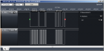
The logic analyzer shows that the address is "0". The two chips communicate just fine with these settings. The Logic analyzer screenshot is of the second write. Address is 0. location is 1 and data is 86. as expected. All 5 writes were successful.
Here is the test code for both chips:
Master:
Slave
I've only dabbled around with the intricacies if I2c. But I've got this neat little Salea logic analyzer that I am testing out. Here's what I've got so far. (Using a 20X2 as Slave and 14M2 as master)
With the 14M2 Master set with : hi2csetup i2cmaster, %00000000, i2cslow_8, i2cbyte
The 14M2 will either hang or reset when it gets to this line. The 20X2 will reset here if set to master.
However, when the address is set to %00000001, it works OK. Bit0 is the W/R bit and is supposed to be ignored. This in effect sets the address to "0", and prevents the Picaxe hangup / reset.
I did the same with the slave. hi2csetup i2cslave, %00000001
The logic analyzer shows that the address is "0". The two chips communicate just fine with these settings. The Logic analyzer screenshot is of the second write. Address is 0. location is 1 and data is 86. as expected. All 5 writes were successful.
Here is the test code for both chips:
Master:
Code:
#picaxe 14M2
#no_Data
#com 1
setfreq M8

pause 1000 'allow slave to get ready
sertxd ("RESETTING PICAXE",cr,lf)      'Test for reset

 hi2csetup i2cmaster,%00000000,i2cslow_8,i2cbyte    'This hangs or reset Picaxe
 hi2csetup i2cmaster,%00000001,i2cslow_8,i2cbyte    'This works ok.  Sets address to 0x00

 b0 = 85   'Data
 b1 = 0    'Location

 do
     hi2cout b1,(b0)
     inc b0
     inc b1
     pause 15
  loop while b0 < 91

  stop
Slave
Code:
'===================================
#Picaxe 20X2
#No_Table
#com 2
Pause 100
'=====================================


'// HI2CSETUP I2CSLAVE,%00000000   ' This will hang  or reset Picaxe
HI2CSETUP I2CSLAVE,%00000001    'This works ok.  Sets address to "0"

main:

   if hi2cflag = 0 then main ; poll flag, else loop

   hi2cflag = 0 ; reset flag
   get hi2clast,b1 ; get last byte written from SP
   sertxd (#b1,cr,lf)

goto main
Attachments
-
 35.9 KB Views: 12
Last edited:
Not sure if it is bug or not. But both the 14M2 and 20X2, when set as a MASTER , will either hang or reset if the slave address is set to %00000000.
I fixed the error in the master code above. Thanks for pointing it out.
I am guessing that you can move along with your code without having to bit-bang by setting the address to %00000001. I would suggest less complex code to start. Something minimal just see if the as1115 responds ....like write a value to a location and then read it back.
Let there be light! Goeytex takes the cake.
Address bit 0 had to be set to 1, but after that still didn't work I had to issue a command to reset to registers. I found that in the C code posted earlier. The first two commands to get the AS1115 working are:
hi2csetup i2cmaster, %00000001, i2cslow_8, i2cbyte
hi2cout 0x0C, (0x01)
I'm actually running a much more complex code than what I posted. I'm driving three 7-segment displays and three 10-segment bar graphs with two pins to the PicAXE! The code I posed is pretyt much the same thing but without the bar graphs.
This is a neat device. Ok, I'm off to play with it now! You guys are awesome.
westaust55
Moderator
From PICAXE manual 2 under the HI2CSETUP command:Not sure if it is bug or not. But both the 14M2 and 20X2, when set as a MASTER , will either hang or reset if the slave address is set to %00000000.
The fact that address $00 (the general call address under the i2c specs) does not work on the PICAXE chips falls into the above category and I believe has been confirmed previously by Technical.Some special i2c addresses (0, %1111xxx, %0000xxxx) have special meanings under the i2c protocol and so are not recommended as they may cause unexpected behaviour on third party devices.
That $01 does work is a good find by Goeytex and work around but cannot be guaranteed to remain a workable solution with future PICAXE chip firmware revisions.