6:9:0 BattmV= 2938,Vcc= 2941,I= 100 mA,PWM= 568
6:9:30 BattmV= 2921,Vcc= 2924,I= 101 mA,PWM= 575
*Log*
6:10:0 BattmV= 2921,Vcc= 2924,I= 100 mA,PWM= 575
6:10:30 BattmV= 2904,Vcc= 2907,I= 100 mA,PWM= 577
6:11:0 BattmV= 2887,Vcc= 2890,I= 100 mA,PWM= 579
6:11:30 BattmV= 2870,Vcc= 2873,I= 100 mA,PWM= 582
6:12:0 BattmV= 2853,Vcc= 2856,I= 100 mA,PWM= 587
6:12:30 BattmV= 2836,Vcc= 2839,I= 100 mA,PWM= 592
6:13:0 BattmV= 2819,Vcc= 2822,I= 99 mA,PWM= 593
6:13:30 BattmV= 2819,Vcc= 2822,I= 100 mA,PWM= 596
6:14:0 BattmV= 2802,Vcc= 2805,I= 100 mA,PWM= 600

6:14:4 BattmV= 2802,Vcc= 2805,I= 58 mA,PWM= 0
6hrs 14mins at 100mA = 620 mAhr,1987 mWhr,5 mins Log
Mins: mV
0  3345
5  3294
10  3294
15  3294
20  3294
25  3294
30  3294
35  3294
40  3294
45  3294
50  3294
55  3294
60  3294
65  3294
70  3294
75  3294
80  3294
85  3294
90  3277
95  3294
100  3277
105  3277
110  3277
115  3277
120  3260
125  3260
130  3260
135  3260
140  3260
145  3260
150  3260
155  3260
160  3260
165  3260
170  3260
175  3260
180  3243
185  3243
190  3243
195  3243
200  3243
205  3243
210  3243
215  3243
220  3243
225  3243
230  3243
235  3243
240  3243
245  3243
250  3226
255  3226
260  3226
265  3226
270  3226
275  3209
280  3209
285  3209
290  3209
295  3192
300  3192
305  3192
310  3192
315  3175
320  3175
325  3158
330  3141
335  3124
340  3124
345  3124
350  3107
355  3090
360  3073
365  3006
370  2921

6:14:4 BattmV= 2972,Vcc= 2975,I= 1 mA,PWM= 0
6hrs 14mins at 100mA = 620 mAhr,1987 mWhr,5 mins Log
Mins: mV
0  3345
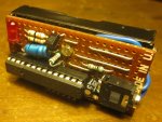
") Good voltage range, cheap, easy to program and good forum. There's my reasons to use Picaxe.
Good voltage range, cheap, easy to program and good forum. There's my reasons to use Picaxe.