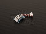
A few newbie questions about the PICAXE-08 Servo Driver Board

sirdakka

New Member
Hi all, new to the forums and a complete noob when it comes to playing around with circuit boards and such.

As part of an experiment I need to move two small components of my apparatus back and forth at irregular intervals and have decide to use the PICAXE-08 servo driver to control two HXT900 servos.

I want to be able to precisely control the time that these components move and so I will be powering the servo driver from a computer controlled amplifier which also controls other aspects of my experiment.
Question1: I was wondering if the 5V pulse TTL that this amplifier supplies is enough to drive the servo driver, as it says that it requires 6V.

Question2 is about how to program the PICAXE-08M2 chip. Whenever I turn on the servo driver by supplying it with a 5V TTL pulse I want it to check the position of each servo motor, and move it to a preset position depending on where each one currently is. Is something like the following possible to program with the chip:

Manually turn power on
If servo 1 is at 0 degrees, then move servo 1 to 120 degrees
Elseif servo 1 is at 120 degrees mover servo 1 to 0 degrees

If servo 2 is at 0 degrees, then move servo 1 to 120 degrees
Elseif servo 1 is at 120 degrees mover servo 1 to 0 degrees

Is it possible to write a program that does the above using the servo driver?

Many thanks for any help and sorry if this is unclear, I will try to explain it better if required.

Josh
 

westaust55

Moderator
Welcome to the PICAXE forum.

Hi all, new to the forums and a complete noob when it comes to playing around with circuit boards and such.

As part of an experiment I need to move two small components of my apparatus back and forth at irregular intervals and have decide to use the PICAXE-08 servo driver to control two HXT900 servos.
Do you already have the board? Is it the AXE024 or another make and model. Please provide a link to what you are/propose to use.

I want to be able to precisely control the time that these components move and so I will be powering the servo driver from a computer controlled amplifier which also controls other aspects of my experiment.
Question1: I was wondering if the 5V pulse TTL that this amplifier supplies is enough to drive the servo driver, as it says that it requires 6V.
The PICAXE can be programmed to directly control the Servo-motors unless there are some specific signals coming from your PC. If that is the case, we need more information about exactly what you are trying to achieve.
I do not foresee that you should need any amplifer.

Question2 is about how to program the PICAXE-08M2 chip.
Have you downloaded and installed the programming Editor software from the Rev Ed PICAXE website?
Do you have an AXE027 or other cable for downloading the program from the PC to the PICAXE?
This cable can also be used to pass other data if necessary

Whenever I turn on the servo driver by supplying it with a 5V TTL pulse I want it to check the position of each servo motor, and move it to a preset position depending on where each one currently is.
A servo motor does not provide any feedback sign that can be used to check the position. The only option might be at add a potentiometer but that is not the usual situation.
You need to send signals/pulses to control the position where you want the servo shaft/horn to be located.
 

sirdakka

New Member
Hi Westaus55

Thank you for your reply.

I have got the AXE027 and downloaded the Editor software and indeed had a play around with it to try to achieve what I require.

Essentially, I have these two components, which, when the experiment reaches a critical point, need to be moved from one place, to another very nearby. This motion can be achieved by HXT900 servos, but the problem is how to program the chip so that the servos respond to my user generated signal, rather than some programmed timing signal.

I understand now that the servos have no memory of their location and so I ask now if there is a way round this problem.

The amplifier which runs the rest of my apparatus will be used merely to supply power to the circuit board, rather than a battery pack. This way I have control through my computer over when the PICAXE-08 receives power. Is it possible to come up with a simple program that is able to move the servos to another position from the one they are currently in when power is supplied? Alternatively, is there an alternative, creative way to solve this problem?

Thanks again, any help is much appreciated
 

BeanieBots

Moderator
Your servos can be told where they need to be by an absolute position request. They do not need to remember anything.
If required, the PICAXE can remember where they were last told to be.

6v is too much for PICAXE. You could use a LDO regulator to drop the 6v down to 5v.

Is it possible to come up with a simple program that is able to move the servos to another position from the one they are currently in when power is supplied?
It is possible to move a servo to a pre-determined position at power up but you will need to tell us more about how/why/where/what it is that determines what that position should be.
 

sirdakka

New Member
Hi BeanieBots,

I essentially want each servo to alternative between two defined positions (A and B for simplicity). I want to be able to tell me servo motors when to move from one position to the other. I want them both to move at the same time and remain there until I tell them to move back. I want to be able to control the servos using my computer, which I am using to send a signal to an amplifier(just a bit of kit which powers the rest of my experiment) which supply the PICAXE-08 board with 5V. Upon supplying the 5V, I want the servos to move from position A to B if they were at A, and position B to A if they were at B.

Do you think this is possible?

Many thanks
 

westaust55

Moderator
Which porgram are you intending to use on your PC to send the required data to the PICAXE chips.

You can use one of several commands in the PICAXE program to received data:
1. SERTXD
2. SERIN
3. HSERIN.

Some of these commands are dedicated to specific PICAXE pins.

Using these commands you can send a value in the range 0 to 255 within a byte variable. This can be scaled or limited to the Servo pulse range (typically 0.75 to 2.25 ms) in the PICAXE program and then the SERVO command used to control the Servo-motor positions.
 

sirdakka

New Member
Could you please give me an example of some code that might be used so that I could control one servo to move between two different positions at user-defined times by supplying power to the picaxe-08 board?

I've played around but still having trouble with this.

Many thanks
 

hippy

Technical Support
Staff member
It would probably be something like this -

Code:
#Picaxe 08M2

Symbol SERVO_PIN   = C.1
Symbol SERVO_POS_1 = 100
Symbol SERVO_POS_2 = 200

Eeprom 0, (1)

Read 0, b0
If b0 = 1 Then
  Servo SERVO_PIN, SERVO_POS_1
  Write 0, 2
Else
  Servo SERVO_PIN, SERVO_POS_2
  Write 0, 1
End If
Do 
  Pause 1000
Loop
Most servos and servo controllers would normally be permanently powered and switch according to some input signal rather than alternate positions at power on.

You may have to add extra hardware to ensure the servo does not twitch when power is initially applied and extra code to control power to the servo.
 
servo code examples

thank you hippy, problem sorted for now :)
I'm a noob myself and it sounds like we are trying to accomplish similar goals. A couple of the same guys that replied to you helped me too and this is what we came up with to move two servos from one end to the other and back again at a nice and slow steady speed:
init:servo 4,75 servo 3,75
main:for b0=75 to 225
servopos 4,b0
servopos 3,b0
pause 50
next
pause 1000

for b1=225 to 75 step-1
servopos 4,b1
servopos 3,b1
pause 50
next
goto main

unlike you, I'm using this through a 18m2 project board with a DIL 330 resistor in place of the darlington chip that came with it.

Problem is, now I'm a bit stuck myself. I tried changing my code so that one servo did 75 to 225 and the other 75 to 150, but they didn't move at the same speed. One moved slow (using the 'pause 50' part of the code), while the other when full speed. I eventually want to move up to seven servos, at the same time, at the same speed, but each to a different angle. Any advice is appreciated. Nice and simple though guys, I can just about programme my microwave as it is.
 

westaust55

Moderator
Problem is, now I'm a bit stuck myself. I tried changing my code so that one servo did 75 to 225 and the other 75 to 150, but they didn't move at the same speed. One moved slow (using the 'pause 50' part of the code), while the other when full speed. I eventually want to move up to seven servos, at the same time, at the same speed, but each to a different angle. Any advice is appreciated. Nice and simple though guys, I can just about programme my microwave as it is.
Untested but try the following for two servos moving in opposite directions at same time.
This only covers travel in one direction but you should be able to add code for the second half of the cycle.

Code:
SYMBOL minpos = 75
SYMBOL maxpos = 225
SYMBOL midpos = maxpos + minpos / 2 ; normally 150
SYMBOL range = maxpos - minpos
SYMBOL currentpos = b0
SYMBOL servo1pos = b1
SYMBOL servo2pos = b2
init:
  servo 4,minpos 
  servo 3,maxpos
main:
  for currentpos = 0 to range 

servo1pos = minpos + currentpos
servo2pos = maxpos - currentpos
servopos 4,servo1pos
servopos 3,servo2po
pause 50
next
pause 1000

goto main
 

sirdakka

New Member
It would probably be something like this -

Code:
#Picaxe 08M2

Symbol SERVO_PIN   = C.1
Symbol SERVO_POS_1 = 100
Symbol SERVO_POS_2 = 200

Eeprom 0, (1)

Read 0, b0
If b0 = 1 Then
  Servo SERVO_PIN, SERVO_POS_1
  Write 0, 2
Else
  Servo SERVO_PIN, SERVO_POS_2
  Write 0, 1
End If
Do 
  Pause 1000
Loop
Most servos and servo controllers would normally be permanently powered and switch according to some input signal rather than alternate positions at power on.

You may have to add extra hardware to ensure the servo does not twitch when power is initially applied and extra code to control power to the servo.
Could you please give me an example of what extra hardware I'd need to use to ensure the servo doesn't twitch when power is initially appplied?
 

hippy

Technical Support
Staff member
Could you please give me an example of what extra hardware I'd need to use to ensure the servo doesn't twitch when power is initially appplied?
It is not my area of expertise and others may be able to offer better information but I would expect you would need a suitable high-side switch circuit to connect power once the servo signal is being generated.

It would really depend on why the servo is jittering and perhaps what make or type of servo is being used. I am guessing jitter is during the period between being powered up and when it locks on to the servo signal. I recall a post on the forum which I think said power-on jitter was resolved in this manner but cannot locate it. If it is other than that it may require more to resolve it.
 

sirdakka

New Member
I have got everything that I asked about working to a satisfactory level. Now I am trying to use a digital input to pin 3, but am confused as to the best way to go about this. If I just solder two wires into the spare pads at the bottom of the board and then connect this to my 5V power supply, the board starts smoking => I am doing something terribly wrong. How should I go about this?
 

hippy

Technical Support
Staff member
If I just solder two wires into the spare pads at the bottom of the board and then connect this to my 5V power supply, the board starts smoking => I am doing something terribly wrong. How should I go about this?
It sounds like you have wired things wrong, either in connecting to the board or have a 5V power supply which does not have a common 0V with the supply powering the AXE024 board, or you are supplying a voltage higher than the PICAXE power supply.

Pin 3 has a 10K pull-down on the AXE024 board so all that is normally needed to bring that input high is to connect Pin3 to the PICAXE supply V+ power rail.

As you seem to be using some sort of 'amplifier' to power the PICAXE it is hard to analyse the cause of the problem without a full wiring diagram including the power supplies. Which part or parts of the board were smoking ?
 

sirdakka

New Member
Hi Hippy, thanks for all your help. I realised I was being a muppet and was shorting something by being silly. I have solved all my problems for now :)
 

sirdakka

New Member
Hey everyone,

I have a few questions concerning servo motors themselves, as I currently have the electronics performing its intended role.

I'm using HXT900 9g servos, and I find them to be very noisy. I am using them in an environment where silence would be ideal, but a small amount of noise is acceptable. Can anyone recommend any particular servo motor that might perform more quietly? Also, is it possible to drive small linear actuators with the PICAXE-08 Servo Driver Board, and if not what would I need to use to power them to perform a similar function to the servos + driver I'm using at the moment?

Once again, thanks for any help with this issue
 

Paix

Senior Member
@Sirdakka, good to hear that you have solved all your problems, but how about sharing the experience with us? What was the cause of the smoking board. Your experience in this matter may be of value, or at least entertainment, to others who may erroniously follow the same initial path as yourself.
 

sirdakka

New Member
Hey all,

As to Paix's request I am going to write a short summary of the project, some things I've learnt and a few mistakes I made. I will also ask a few questions which I still have and hopefully the extremely high level of input, of which I'm extremely grateful, continues :)

I am using the Picaxe servo driver to drive two HXT 900 servos, which are used to manipulate two small mechanisms which I'm rigging up as an autofeeder for my pet mice's cage. Essentially, the mice can press a lever in their cage, and food is dispensed to them and this is great environmental enrichment for two inquisitive animals.

I had a huge amount of help from the forums in terms of writing the code for the program, as I have little experience of this, but that is no longer an issue. Thanks for all the input.

However, when playing around with rewiring to include an external switch input on pin 3 I was mistakenly supplying power to this pin, rather than connecting the circuit, and this was the cause of the board smoking. I soon realised what a muppet I was being and didn't do too much damage :p

My most recent problem however, is that the mice hate the noise of the servos. I've tried using the suggested code from the servo driver manual, which involves moving through each degree with a small delay inbetween thus slowing the speed of the motion, but they hate this just as much.

I really don't want to abandon the project so close to completion and having spent so much time on the food release mechanism, and so I would be incredibly grateful if anyone could suggest how I could reduce noise. I thought about placing extra resistors in between the chip and the servos to slow them down that way, but I have no idea if that would be a waste of time/damage the circuit. Does anyone know of any cheap(ish) servos with relatively quiet operating noise? Also, would greasing up the gears make any difference?

Thanks again to the community.
 
Last edited:

Paix

Senior Member
Thanks for the roadmap, past and future; it puts all things into context.

I think that adding resistors to the servo signal path will not affect the speed, which is determined by the proportional pulse length and not the amplitude.
I believe that a small resistance may be used for isolation and to protect the Picaxe servo output pin in the case of a fault, but have no personal experience of doing that and believe it to be unnecessary.

With regard to the noise frightening the mice, I suspect that this isn't a circuit issue, but a mouse one. They are easily startled, have good hearing and a healthily nervous disposition that is designed to stop them getting eaten by predators. I can only really suggest that remoting the servos from the feeding mechanism by the use of bell cranks and piano wire would allow you to essentially place the servos in a sound damped enclosure. So a mechanical solution to solve that problem perhaps.

There have been Picaxe carp feeders in the past and a problem encountered was greedy carp. Perhaps a time delay after feeding, with an LED as feedback so the mice get to know that when a green LED is on feeding is possible, but a red LED lighting for a specified time after feeding would indicate that seconds were not available. Of course with more than one mouse this can only be a generalisation which you will have to think about and refine to meet your needs. Getting it wrong might produce a fat mouse and a very skinny one . . . :)
 

sirdakka

New Member
I didn't intend to add resistance to the signal pin, but rather the pin that sends voltage to the motor; does that not reduce servo speed?
 

Paix

Senior Member
Ahhhh, on both counts. OK on the resistor and ouch, I never really thought about mouse vision being monochrome. Next I'll find out that it's 405 lines too :) 625 for the younger members.
 

Buzby

Senior Member
....I never really thought about mouse vision being monochrome....
It doesn't matter if they are colour blind, they will recognise the LED's positions. ( Assuming you are using two LEDs, not a single bicolour LED. )
 

sirdakka

New Member
Ahhhh, on both counts. OK on the resistor and ouch, I never really thought about mouse vision being monochrome. Next I'll find out that it's 405 lines too :) 625 for the younger members.

how much resistance would I need to put in to slow down by 1/2 ? By 1/4? etc.
 

Paix

Senior Member
I don't know, but suggest that whilst you may have a limited degree of control over the motor speed, but there is also a control board inside the servo.
I'm not familiar with the detail, so you may quite easily compromise the servo and end up with unreliable operation.
I wouldn't think that you are likely to reliably achieve even half speed by reducing the supply voltage to the servo within whatever safe limits are available.
Given that the quest is for quiet operation rather than variable speed of operation, which could be controlled by the Picaxe program code, how practical is the idea of remoting the mechanics and using a bell crank and stiff piano wire to achieve quieter operation?
 

sirdakka

New Member
Remoting the mechanics as you recommend is a good idea, and have been investigating that possiblity. What thickness of wire would you recommed? I'm looking at http://www.squirestools.com/12-19a.pdf page 344 as they have a whole range of 36" piano wire but I'm not sure what is the best balance between stiffness and lightness. Can you suggest anything please?
 

sirdakka

New Member
Hey All,

I'm resurrecting this thread, as I have reached a problem with the aforementioned project which I am struggling to solve. Having got everything set up and working for the last 4 months, yesterday I observed a failure in the system which I have been unable to rectify.

First off, I am using a PICAXE-08 servo controller board to drive two servos using the following code:

Code:
#Picaxe 08M2

Symbol LEVER_SERVO = C.2
Symbol SPOUT_SEVO = C.1
Symbol LEVER_POS_UL = 150
Symbol LEVER_POS_L = 100
Symbol SPOUT_POS_IN = 100
Symbol SPOUT_POS_OUT = 150

Eeprom 0, (1)

Servo SPOUT_SERVO, SPOUT_POS_OUT
Servo LEVER_SERVO, LEVER_POS_L

Read 0, b0
If b0 = 1 Then
   Servo LEVER_SERVO, LEVER_POS_L
   Write 0, 2
Else
   Servo LEVER_SERVO, LEVER_POS_UL
   Write 0, 1
End If
Do
If pinC.3 = 1 Then
Read 0, b0
   If b0=1 Then
   Pause 500
   Servo SPOUT_SERVO, SPOUT_POS_IN
   Pause 1000
   Servo LEVER_SERVO, LEVER_POS_L
   Pause 1500
   Servo SPOUT_SERVO, SPOUT_POS_OUT
   Servo LEVER_SERVO, LEVER_POS_UL
   End If
End If
Pause 150
Loop
I am using pin 3 as an input pin to initiate the second loop, but since yesterday, whenever an input is provided, after SPOUT_SERVO and LEVER_SERVO return to position OUT and UL respectively, LEVER_SERVO starts to oscillate continuously between L and UL for 10-20 seconds. This can be stopped by removing SPOUT_SERVO.

I have replaced every component of the system: tried a different servo controller board, replaced the servo motors, replaced all cabling, removed input to pin 3 etc. but the problem still persists. We haven't changed the code above in 4 months.

About a month ago LEVER_SERVO started to make some sort of low volume buzzing noise. This noise is now slightly louder, and changes pitch depending on whether SPOUT_SERVO is also plugged in to the board. It appears that all of a sudden there is some interaction error between the two servo motors, as when running the above code with only one servo motor plugged in, it does its job properly. I only see the aforementioned problem when both are connected.

Any advice would be much appreciated.

Cheers,

Sirdakka
 
Last edited by a moderator:

Rick100

Senior Member
Hello Sirdakka,
Try using the "servo" command once for each servo at the top of the program to define the servo pin. Then use "servopos" in the body of the program to adjust the positions.

Good luck,
Rick
 

sirdakka

New Member
Hello Sirdakka,
Try using the "servo" command once for each servo at the top of the program to define the servo pin. Then use "servopos" in the body of the program to adjust the positions.

Good luck,
Rick
Sorry, could you elaborate please? I'm just following the syntax suggested in the Picaxe Programming Editor help files.
 

Rick100

Senior Member
Sorry, could you elaborate please? I'm just following the syntax suggested in the Picaxe Programming Editor help files.
Look at the example for servopos at the bottom of the page:
http://www.picaxe.com/BASIC-Commands/Digital-InputOutput/servopos/
It shows the correct usage.

And from the "servo" command documentation:
http://www.picaxe.com/BASIC-Commands/Digital-InputOutput/servo/

The servo command initialises the pin for servo operation and starts the timer.
Once a pin has been initialised, it is recommended to use the servopos command to adjust position. This prevents resetting of the timer, which could cause 'jitter'
Good luck,
Rick
 

sirdakka

New Member
Hi Rick,

I have followed your advice and edited the code so that only the first instance of positioning the servos used the "Servo" command, and every later instance the "Servopos" command. However, I am still getting this humming noise and oscillatory behaviour of LEVER_SERVO at the end of the last If loop.

However, if I unplug SPOUT_SERVO, I no longer get the oscillatory behaviour and a lower pitch of humming from LEVER_SERVO. I believe that the two motors are having some sort of feedback issue which affects each other.

This is a brand new problem in a system unchanged in 4 months. As I mentioned I have completely replaced every part of the system from PICAXE-08 circuit to servo motors. I am still stumped.
 

Goeytex

Senior Member
Have you checked the power supply(s) for correct voltage and noise/ ripple?

With your meter on the supply voltage for the servos, monitor the voltage while operating the servos. Do the same on the Picaxe V+ pin.
Does the voltage drop ?


Is the Picaxe resetting? Temporarily add "disablebod" at the start of the code. Does the behavior change?
Try adding the following lines after the EEPROM statement:

Pause 2000
sertxd ("Starting program")

Run the program. Do you see "starting program" in the terminal more than once ?

Is there a mechanical drag on one of the valves causing the servo to draw excessive current?
 
Last edited:

Rick100

Senior Member
Hello sirdakka,

I agree with Goeytex's suggestions. Apparantly the HXT900 servos can draw a peak of 750ma. Two of them running at the same time could draw 1.5 amps. What are you using for a power supply? Do the servos and Picaxe have the same power supply?

Good luck,
Rick
 

sirdakka

New Member
Thank you for all your suggestions. I'm a muppet; the problem was with the power source... Rather embarrassed :p

Cheers,

Sirdakka
 

sirdakka

New Member
Hi All,

Once again resurrecting the thread. I'm looking to modify my code so that there are two inputs. I've set things up as you can see below, but the loop called when input C.4 is High doesn't work as expected. Is my syntax correct? I'm sure I've just made some silly mistake and would much appreciate someone to proof read my code.

Many thanks!

Code:
#Picaxe 08M2

; Servo Control script in conjunction with Arduino- controlled 
; Cued Lever paradigm

;servo1 controls the spout, BRO
;servo2 controls the lever, BGY
;correct as of 29/7/15

Symbol LEVER_SERVO   = C.1
Symbol SPOUT_SERVO   = C.2
Symbol LEVER_POS_UL = 100 	    ;unlocked position
Symbol LEVER_POS_L = 150 	      ;locked position
Symbol SPOUT_POS_IN = 100 	    ;spout in
Symbol SPOUT_POS_OUT = 150 	;spout away
Input C.4 					

Eeprom 0,(1)

Servo SPOUT_SERVO, SPOUT_POS_OUT

Read 0, b0		; Power cycle to switch between lever locked positions
If b0 = 1 Then
	Servo LEVER_SERVO, LEVER_POS_L
	Write 0, 2
Else
	Servo LEVER_SERVO, LEVER_POS_UL
	Write 0, 1
End If

Do

	If pinC.4 = 1 Then	; If ServoReset HIGH detected then...
		Read 0, b0
		
		If b0 = 1 Then	;  If LEVER_SERVO in UL position then...
			Servo LEVER_SERVO, LEVER_POS_L
			Pause 200
			Servo LEVER_SERVO, LEVER_POS_UL
		End If
		
	End If
	
	If pinC.3 = 1 Then	; If RewardSignalOut HIGH detected then...
		Read 0, b0
		
		If b0 = 1 Then	; If LEVER_SERVO in UL position then...
			Servo SPOUT_SERVO, SPOUT_POS_IN
			Pause 2000
			Servo SPOUT_SERVO, SPOUT_POS_OUT
			Pause 1000
			Servo LEVER_SERVO, LEVER_POS_L
			Pause 500
			Servo LEVER_SERVO, LEVER_POS_UL
		End If
		
	End If


	Pause 200
	
Loop
 

rossko57

Senior Member
You seem to have forgotten the advice about using servopos.

Can you tell us what behaviour you expected, and what actually happens instead? 200mS doesn't seem a very long pause between repositions.
 
Top