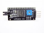
Picaxe 18M2+ and I2C LCD 16x2 display

nick12ab

Senior Member
Welcome to the PICAXE Forum.

Your LCD is one of those where they have got an i2c I/O expander chip and wired it to the LCD in 4-bit mode. Searching does not produce any complete solutions for using these displays.

The i2c address (7-bit) is $27 so when using the hi2csetup command on PICAXE, you'll need to specify the address as $4E because PICAXE uses an '8-bit address' which includes the read/write bit (which is changed automatically when a hi2cin or hi2cout command is executed).

Could you please check exactly which port expander IC you have on that board, then check with a multimeter which pin on the LCD display is connected to which pin on the i2c port expander's data bus. One pin might connect to a transistor which then controls the backlight.

Once you have found that out, you can then modify the LCD code in PICAXE Manual 3 so that instead of sending the resultant bytes to the output pins, they are sent to the LCD with a hi2cout command instead, after making sure that the bits are in the correct order.
 

westaust55

Moderator
What information, if any, did you receive when you purchased the display. There is very little data or code examples easily found on the internet.

Here is some information I found for the i2c LCD module you have:

Specification
# I2C Address: 0x20
# Supply voltage: 5V
# Size: 82x35x18 mm
# Come with IIC interface, which can be connected by DuPont Line
and C programming code:
Code:
#include <Wire.h> 
#include <LiquidCrystal_I2C.h>
LiquidCrystal_I2C lcd(0x20,16,2); //set the LCD address to 0x20 for a 16 chars and 2 line display
void setup()
{
lcd.init(); 
lcd.backlight();
lcd.setCursor(0, 0);
lcd.print("Hello");
lcd.setCursor(0, 1);
lcd.print("Voltage: ");
lcd.setCursor(13, 1);
lcd.print("V");
}
void loop()
{
int val;
float temp;
val=analogRead(0);
temp=val/4.092;
val=(int)temp;//
lcd.setCursor(9, 1);
lcd.print(0x30+val/100,BYTE); 
lcd.print(0x30+(val%100)/10,BYTE); 
lcd.print('.');
lcd.print(0x30+val%10,BYTE);
delay(100);
But you need the header file LiquidCrystal_I2C.h to have a quicker way to determine the PICAXE program requirements.

If you delve into this website it may help you: https://bitbucket.org/fmalpartida/new-liquidcrystal/wiki/Home
More specifically this sub-page: http://www.electrofunltd.com/2011/10/i2c-lcd-extra-io.html#!/2011/10/i2c-lcd-extra-io.html


The I2C expander chip is the PCF8574T
The datasheet for that chip can be found here: http://www.nxp.com/documents/data_sheet/PCF8574.pdf
 

Attachments

akard

New Member
Many thanks to all.
I had no information on purchase the device and I not found picaxe program example on it.
The only examples on the net was for arduino.
I need help to implement a simple scratch to try this device.
Thanks.
 

nick12ab

Senior Member
I need help to implement a simple scratch to try this device.
I found this schematic at one of WestAust55's links:


However it is for a product that they sell which looks different to the one that you bought which is why you need to check your PCB to find out which pin goes where on your PCB.
 

westaust55

Moderator
From what I read yesterday, there seems to be an enhanced Arduino i2c driver (or two) written by the A* community to add LCD interfacing to a library. It is a case of finding that C library file and confirming IO Expander pin usage as nick12ab has suggested.
I saw references to a similar i2c. Interface with a slave address of $27 but from the photos of the GY-IiC-1602 module it seems the three adress pins are all tied low so $20 would seemngly to be appropriate.

Likely no one here has previously written a suitable piece of PICAXE code so this could be the first time.
It will be similar to code send via a parallel interface but sending the data over the i2c bus.
However the connections on the board must be confirmed before anyone can/will write code.
 
Last edited:

nick12ab

Senior Member
It is a case of finding that C library file
The library files can be found on most eBay listings that sell these modules.

LiquidCrystal_I2C.cpp
Code:
//YWROBOT
#include "LiquidCrystal_I2C.h"
#include <inttypes.h>
#include "WProgram.h" 
#include "Wire.h"


// When the display powers up, it is configured as follows:
//
// 1. Display clear
// 2. Function set: 
//    DL = 1; 8-bit interface data 
//    N = 0; 1-line display 
//    F = 0; 5x8 dot character font 
// 3. Display on/off control: 
//    D = 0; Display off 
//    C = 0; Cursor off 
//    B = 0; Blinking off 
// 4. Entry mode set: 
//    I/D = 1; Increment by 1
//    S = 0; No shift 
//
// Note, however, that resetting the Arduino doesn't reset the LCD, so we
// can't assume that its in that state when a sketch starts (and the
// LiquidCrystal constructor is called).

LiquidCrystal_I2C::LiquidCrystal_I2C(uint8_t lcd_Addr,uint8_t lcd_cols,uint8_t lcd_rows)
{
  _Addr = lcd_Addr;
  _cols = lcd_cols;
  _rows = lcd_rows;
  _backlightval = LCD_NOBACKLIGHT;
}

void LiquidCrystal_I2C::init(){
	init_priv();
}

void LiquidCrystal_I2C::init_priv()
{
	Wire.begin();
	_displayfunction = LCD_4BITMODE | LCD_1LINE | LCD_5x8DOTS;
	begin(_cols, _rows);  
}

void LiquidCrystal_I2C::begin(uint8_t cols, uint8_t lines, uint8_t dotsize) {
	if (lines > 1) {
		_displayfunction |= LCD_2LINE;
	}
	_numlines = lines;

	// for some 1 line displays you can select a 10 pixel high font
	if ((dotsize != 0) && (lines == 1)) {
		_displayfunction |= LCD_5x10DOTS;
	}

	// SEE PAGE 45/46 FOR INITIALIZATION SPECIFICATION!
	// according to datasheet, we need at least 40ms after power rises above 2.7V
	// before sending commands. Arduino can turn on way befer 4.5V so we'll wait 50
	delayMicroseconds(50000); 
  
	// Now we pull both RS and R/W low to begin commands
	expanderWrite(_backlightval);	// reset expanderand turn backlight off (Bit 8 =1)
	delay(1000);

  	//put the LCD into 4 bit mode
	// this is according to the hitachi HD44780 datasheet
	// figure 24, pg 46
	
	// we start in 8bit mode, try to set 4 bit mode
	write4bits(0x03);
	delayMicroseconds(4500); // wait min 4.1ms
	
	// second try
	write4bits(0x03);
	delayMicroseconds(4500); // wait min 4.1ms
	
	// third go!
	write4bits(0x03); 
	delayMicroseconds(150);
	
	// finally, set to 4-bit interface
	write4bits(0x02); 


	// set # lines, font size, etc.
	command(LCD_FUNCTIONSET | _displayfunction);  
	
	// turn the display on with no cursor or blinking default
	_displaycontrol = LCD_DISPLAYON | LCD_CURSOROFF | LCD_BLINKOFF;
	display();
	
	// clear it off
	clear();
	
	// Initialize to default text direction (for roman languages)
	_displaymode = LCD_ENTRYLEFT | LCD_ENTRYSHIFTDECREMENT;
	
	// set the entry mode
	command(LCD_ENTRYMODESET | _displaymode);
	
	home();
  
}


/********** high level commands, for the user! */
void LiquidCrystal_I2C::clear(){
	command(LCD_CLEARDISPLAY);// clear display, set cursor position to zero
	delayMicroseconds(2000);  // this command takes a long time!
}

void LiquidCrystal_I2C::home(){
	command(LCD_RETURNHOME);  // set cursor position to zero
	delayMicroseconds(2000);  // this command takes a long time!
}

void LiquidCrystal_I2C::setCursor(uint8_t col, uint8_t row){
	int row_offsets[] = { 0x00, 0x40, 0x14, 0x54 };
	if ( row > _numlines ) {
		row = _numlines-1;    // we count rows starting w/0
	}
	command(LCD_SETDDRAMADDR | (col + row_offsets[row]));
}

// Turn the display on/off (quickly)
void LiquidCrystal_I2C::noDisplay() {
	_displaycontrol &= ~LCD_DISPLAYON;
	command(LCD_DISPLAYCONTROL | _displaycontrol);
}
void LiquidCrystal_I2C::display() {
	_displaycontrol |= LCD_DISPLAYON;
	command(LCD_DISPLAYCONTROL | _displaycontrol);
}

// Turns the underline cursor on/off
void LiquidCrystal_I2C::noCursor() {
	_displaycontrol &= ~LCD_CURSORON;
	command(LCD_DISPLAYCONTROL | _displaycontrol);
}
void LiquidCrystal_I2C::cursor() {
	_displaycontrol |= LCD_CURSORON;
	command(LCD_DISPLAYCONTROL | _displaycontrol);
}

// Turn on and off the blinking cursor
void LiquidCrystal_I2C::noBlink() {
	_displaycontrol &= ~LCD_BLINKON;
	command(LCD_DISPLAYCONTROL | _displaycontrol);
}
void LiquidCrystal_I2C::blink() {
	_displaycontrol |= LCD_BLINKON;
	command(LCD_DISPLAYCONTROL | _displaycontrol);
}

// These commands scroll the display without changing the RAM
void LiquidCrystal_I2C::scrollDisplayLeft(void) {
	command(LCD_CURSORSHIFT | LCD_DISPLAYMOVE | LCD_MOVELEFT);
}
void LiquidCrystal_I2C::scrollDisplayRight(void) {
	command(LCD_CURSORSHIFT | LCD_DISPLAYMOVE | LCD_MOVERIGHT);
}

// This is for text that flows Left to Right
void LiquidCrystal_I2C::leftToRight(void) {
	_displaymode |= LCD_ENTRYLEFT;
	command(LCD_ENTRYMODESET | _displaymode);
}

// This is for text that flows Right to Left
void LiquidCrystal_I2C::rightToLeft(void) {
	_displaymode &= ~LCD_ENTRYLEFT;
	command(LCD_ENTRYMODESET | _displaymode);
}

// This will 'right justify' text from the cursor
void LiquidCrystal_I2C::autoscroll(void) {
	_displaymode |= LCD_ENTRYSHIFTINCREMENT;
	command(LCD_ENTRYMODESET | _displaymode);
}

// This will 'left justify' text from the cursor
void LiquidCrystal_I2C::noAutoscroll(void) {
	_displaymode &= ~LCD_ENTRYSHIFTINCREMENT;
	command(LCD_ENTRYMODESET | _displaymode);
}

// Allows us to fill the first 8 CGRAM locations
// with custom characters
void LiquidCrystal_I2C::createChar(uint8_t location, uint8_t charmap[]) {
	location &= 0x7; // we only have 8 locations 0-7
	command(LCD_SETCGRAMADDR | (location << 3));
	for (int i=0; i<8; i++) {
		write(charmap[i]);
	}
}

// Turn the (optional) backlight off/on
void LiquidCrystal_I2C::noBacklight(void) {
	_backlightval=LCD_NOBACKLIGHT;
	expanderWrite(0);
}

void LiquidCrystal_I2C::backlight(void) {
	_backlightval=LCD_BACKLIGHT;
	expanderWrite(0);
}


/*********** mid level commands, for sending data/cmds */

inline void LiquidCrystal_I2C::command(uint8_t value) {
	send(value, 0);
}

inline void LiquidCrystal_I2C::write(uint8_t value) {
	send(value, Rs);
}


[B]/************ low level data pushing commands **********/

// write either command or data
void LiquidCrystal_I2C::send(uint8_t value, uint8_t mode) {
	uint8_t highnib=value&0xf0;
	uint8_t lownib=(value<<4)&0xf0;
       write4bits((highnib)|mode);
	write4bits((lownib)|mode); 
}

void LiquidCrystal_I2C::write4bits(uint8_t value) {
	expanderWrite(value);
	pulseEnable(value);
}

void LiquidCrystal_I2C::expanderWrite(uint8_t _data){                                        
	Wire.beginTransmission(_Addr);
	Wire.send((int)(_data) | _backlightval);
	Wire.endTransmission();   
}

void LiquidCrystal_I2C::pulseEnable(uint8_t _data){
	expanderWrite(_data | En);	// En high
	delayMicroseconds(1);		// enable pulse must be >450ns
	
	expanderWrite(_data & ~En);	// En low
	delayMicroseconds(50);		// commands need > 37us to settle
} [/B]


// Alias functions

void LiquidCrystal_I2C::cursor_on(){
	cursor();
}

void LiquidCrystal_I2C::cursor_off(){
	noCursor();
}

void LiquidCrystal_I2C::blink_on(){
	blink();
}

void LiquidCrystal_I2C::blink_off(){
	noBlink();
}

void LiquidCrystal_I2C::load_custom_character(uint8_t char_num, uint8_t *rows){
		createChar(char_num, rows);
}

void LiquidCrystal_I2C::setBacklight(uint8_t new_val){
	if(new_val){
		backlight();		// turn backlight on
	}else{
		noBacklight();		// turn backlight off
	}
}

void LiquidCrystal_I2C::printstr(const char c[]){
	//This function is not identical to the function used for "real" I2C displays
	//it's here so the user sketch doesn't have to be changed 
	print(c);
}


// unsupported API functions
void LiquidCrystal_I2C::off(){}
void LiquidCrystal_I2C::on(){}
void LiquidCrystal_I2C::setDelay (int cmdDelay,int charDelay) {}
uint8_t LiquidCrystal_I2C::status(){return 0;}
uint8_t LiquidCrystal_I2C::keypad (){return 0;}
uint8_t LiquidCrystal_I2C::init_bargraph(uint8_t graphtype){return 0;}
void LiquidCrystal_I2C::draw_horizontal_graph(uint8_t row, uint8_t column, uint8_t len,  uint8_t pixel_col_end){}
void LiquidCrystal_I2C::draw_vertical_graph(uint8_t row, uint8_t column, uint8_t len,  uint8_t pixel_row_end){}
void LiquidCrystal_I2C::setContrast(uint8_t new_val){}
LiquidCrystal_I2C.h is unimportant for this - it contains little more than a list of command numbers you can get from the HD44780 datasheet. If you want to see it, it will be in the attached zip folder.

The important bit is the 'low level data pushing commands' part, in LiquidCrystal_I2C.cpp.

If I obtain one of these modules and no one else has written PICAXE BASIC code for one by then, I will write the code. However I have no intention of paying for one so that will take a while.
 

Attachments

hippy

Technical Support
Staff member
Untested and the SYMBOL definitions will likely have to be adjusted ...

Code:
Symbol  LCD_ADR   = $20       ; I2C Address of LCD

Symbol  DB4       = bit0      ; LCD Data Line 4
Symbol  DB5       = bit1      ; LCD Data Line 5
Symbol  DB6       = bit2      ; LCD Data Line 6
Symbol  DB7       = bit3      ; LCD Data Line 7
Symbol  RS        = bit4      ; 0 = Command   1 = Data
Symbol  RD        = bit5      ; 0 = Write     1 = Read
Symbol  E         = bit6      ; 0 = Idle      1 = Active

Symbol  RSCMD     = 0         ; Select Command register
Symbol  RSDAT     = 1         ; Select Data register

Symbol  reserved  = b0
Symbol  fetch     = b1
Symbol  char      = b2

PowerOnReset:

      Gosub InitialiseLcd

DisplayTopLine:

      Eeprom 6,("Hello")

      For fetch = 6 TO 10
        Read fetch,char
        Gosub SendDataByte
      Next

MoveCursorToStartOfSecondLine:

      char = $C0
      Gosub SendCmdByte

DisplayBottomLine:

      Eeprom 11,("World!")

      For fetch = 11 To 16
        Read fetch,char
        Gosub SendDataByte
      Next

      End

InitialiseLcd:

      HI2cSetup I2CMASTER, LCD_ADR, I2CSLOW, I2CBYTE

      For fetch = 0 To 5
        Read fetch,char
        Gosub SendInitCmdByte
      Next

      ' Nibble commands - To initialise 4-bit mode

      Eeprom 0,( $33 )    ; %0011---- %0011----   8-bit / 8-bit
      Eeprom 1,( $32 )    ; %0011---- %0010----   8-bit / 4-bit

      ' Byte commands - To configure the LCD

      Eeprom 2,( $28 )    ; %00101000 %001LNF00   Display Format
      Eeprom 3,( $0C )    ; %00001100 %00001DCB   Display On
      Eeprom 4,( $06 )    ; %00000110 %000001IS   Cursor Move

                          ; L : 0 = 4-bit Mode    1 = 8-bit Mode
                          ; N : 0 = 1 Line        1 = 2 Lines
                          ; F : 0 = 5x7 Pixels    1 = N/A
                          ; D : 0 = Display Off   1 = Display On
                          ; C : 0 = Cursor Off    1 = Cursor On
                          ; B : 0 = Cursor Steady 1 = Cursor Flash
                          ; I : 0 = Dec Cursor    1 = Inc Cursor
                          ; S : 0 = Cursor Move   1 = Display Shift

      Eeprom 5,( $01 )    ; Clear Screen

      Return

SendInitCmdByte:

      Pause 15                        ; Delay 15mS

SendCmdByte:

      RS  = RSCMD                     ; Send to Command register

      RD = 0                          ; Write to the display
       
SendDataByte:

      DB4 = char / %00010000          ; Put MSB out first
      DB5 = char / %00100000
      DB6 = char / %01000000
      DB7 = char / %10000000

      E   = 0 : HI2cOut( b0 )         ; Pulse E
      E   = 1 : HI2cOut( b0 )
      E   = 0 : HI2cOut( b0 )

      DB4 = char / %00000001          ; Put LSB out second
      DB5 = char / %00000010
      DB6 = char / %00000100
      DB7 = char / %00001000

      E   = 0 : HI2cOut( b0 )         ; Pulse E
      E   = 1 : HI2cOut( b0 )
      E   = 0 : HI2cOut( b0 )

      RS  = RSDAT                     ; Send to Data register Next

      Return
 

John West

Senior Member
This appears to be another case where the original thread poster was asked to provide a bit of essential information, but failed to. Those looking for solutions to their problems need to understand that they too need to be a party to the solving of their problem. Nothing ventured, nothing gained.
 

struggles

New Member
I too found myself buying this type of display without looking for software first. Fortunately I got the display to work with a picaxe 28x2. Attached is the code. Don't forget to read the notes: the display I got had a different address than what the vendor stated.
 

Attachments

westaust55

Moderator
@stuggles,

welcome to the PICAXE forum.

Well done on getting your own i2c comms based LCD module working.

With respect to the "different" slave address, you may wish to consider the following advise which I provided in another thread recently for a different i2c device.
Many datasheets give a 7-bit slave address. When this is done, the. Slave adress is placed in the upper 7 bits of the PICAXE slave address value. The least significant bit (bit 0) is for the read /write but which the PICAXE firmware will set/clear as appropriate depending in whether you use Hi2cout or Hi2cin commands.
Occasionally a Datasheet gives two slave addresses as one for read and the second for write where the only different is the lsb.

Thus the $71 (%x1110001) given in the display Datasheet when inserted into the slave address becomes %1110001x or $E2.​

For the same reason $20 = %00100000 when placed into the upper 7 bits of the address bytes is as you say %01000000 = $40.
Such information may well help akard as the original poster for this thread.
 

Peter-C

Member
I too have one of these horrid little units with no documentation, and having spent the day trying to make it do something (anything!) I came across this earlier thread from August 2012:
http://www.picaxeforum.co.uk/showthread.php?21872-Using-Arduino-IIC-I2C-Serial-3-2-quot-LCD-2004-Module-Display/page5

I can confirm that this code of Hippy's in post #28 of that thread does produce an output on this LCM1602 IIC board with a 16X2 LCD. Also, the problem of the backlight switch is also resolved in the thread.

The address of the unit with all three jumpers shorted is 0x20 and the code works with $40 in the line: HI2cSetup I2CMASTER, $40, I2CSLOW, I2CBYTE

Maybe this can save others some time? As ever, thanks to Hippy!
 

struggles

New Member
@westaust55

Thank you for the welcome note.
I agree with your quote and probably read that in a forum thread somewhere because the text looks familiar to me. I actually put something similar in the notes at the top of the code example but that is not readily visible in the thread without opening the document.

I should also take a few seconds to thank Hippy and Technical for the information they provided in the various threads on what the hi2cout command actually sends out. That was my main sticking point as the manual only shows the form 0,(x,y,..), but I couldn't find the actual purpose of the 0. However sending it will definitely mess up the display's initialization sequence and at that point your stuck with nothing. Its only when the display shows some text that it becomes surprisingly easy to drive.
 

Captain Haddock

Senior Member
A big thank you to Struggles from me, I posed a question about a similar unit a while ago and decided to buy 3 of them, when they turned up I had a brief play with no joy but didn't have time to have a proper play, have just hooked one up to a 40x2 with your screentest.bas prog above (with the address adjusted) and it's worked straight away, now have to find time to continue learning how to use it properly.
Me a happy bunny :)
 

Captain Haddock

Senior Member
OK assistance now required, how the hell do I control the backlight?
I'm fairly sure the backlight is controled via a transistor on i/o 7 but can't get my head around how to do it.
Code I'm using is modded from Struggles screentest.bas and is as follows.
Code:
#picaxe 40x2
symbol LCD_ID = $4e		
symbol counter = b4		' loop counter
symbol Rs = b6		      ' display's Rs line = P6 on PCF8574
symbol Enable = 16	      ' display's Enable line = P4 on PCF8574

init:
	setfreq m8
	hi2csetup i2cmaster, LCD_ID, i2cslow, i2cbyte
	gosub InitDisplay
main:	
	
	b0 = 1:gosub wrins 'clear screen
	b0 = 128:gosub wrins 'set cursor pos
	for counter = 0 to 13
		lookup counter,("This is a test "),b0
		gosub wrchr
	next counter
	pause 2000
	b0 = 1:gosub wrins 'clear screen
	pause 1000
	goto main
	
InitDisplay:
	pause 200 		hi2cout 3,(19,3)
	pause 5			 ' Wait 5 ms
	hi2cout (19,3)		' Send data again
	hi2cout (19,3)		' Send data again
	hi2cout (18,2)	
	b0 = 40
	gosub wrins
	b0 =  12 ' display control: turn on screen
	gosub wrins
	return

' --------- low level subroutines ---------------------------------
wrins: 
	Rs=0		' instruction
	goto chrout
wrchr: 
	Rs=64		' character
chrout:
	b1 = b0 / 16	' high nibble
	gosub send_nibble
	b1 = b0 & 15	' low nibble
send_nibble:
	b1 = b1 | Rs
	b2 = b1 | Enable
	HI2cOut [LCD_ID],b1,(b2,b1)
	return
Any pointers appreciated, have looked through the threads linked and just not getting it.
 

nick12ab

Senior Member
I'm fairly sure the backlight is controled via a transistor on i/o 7 but can't get my head around how to do it.
You need to OR the data byte (for the port output pins) with $80 every time you send it to the i2c display if you want the backlight to be on. When you don't do it, the backlight will turn off.

This is assuming you've got the pin for the transistor correct.
 

Peter-C

Member
If we have the same LCM1602 IIC units then try this for the backlight switch:

1/ Declare a symbol Symbol bitBKL = bit11 'Backlight switch on 1602 module
then place a line in one of the subroutines bitBKL = 1 'turns backlight on or off, 1 is on.

Using Hippys code, I placed it in the SendB0AsInitByte: routine

Works for me!
 
Top