PICAXE has the irout command but it is very limited - not only can it only do the SIRC protocol but you can only set the command and not the device. I couldn't find much at all about bit-banging proper IR interfaces on PICAXE - there was plenty of info on using serout instead but that can't be used to control other devices.
RC-5 looks like an easy interface to bit bang. There are few bits and it uses manchester encoding rather than the popular alternative of varying pauses depending on whether the bit is a 1 or 0. That is important as it means that there is now only one time period value to guess rather than two values (you can't just use a pauseus command with the value pulled from the specification due to the overhead of the interpreter) plus the inverted part of the bit can be generated really easily.

I used a PICAXE-14M2 at 32MHz.
In this example code, signalpin is a pin variable (remember to set the pin as an output first!), bitperiod is a constant, flipbit/addressx/datax are bit variables. The flipbit bit variable should be toggled so that it indicates whether any interruption in the signal was because of something blocking the signal or because the button was released and pressed again.
The addressx bits control which device is to be controlled and the datax bits control what command is to be sent to the device.
The placement of the data6 bit is believed to be correct but it might not be because the Wikipedia article wasn't 100% clear about it.
If multiple devices need to be controlled then the addressx bits can be assigned to variables - if not then they can be constants. If 4 or less (2 or less if using data6) devices are to be controlled, the relevant addressx bits can use the remaining bit variables that are part of the same byte variable as the datax bits are part of allowing the device controlled and the command sent to both be set using a single let command. Any number of devices can be controlled this way if a word variable is used.
I will use the above technique in the example below that can control a TV and a set top box.
This example code can control six functions of the TV or STB using six buttons wired between the pins defined in the symbol definitions and 0V - the internal pullups are used. The datasent bit variable is used to determine whether to toggle the flipbit variable or not. The pause 800 added to the send sub is to create a delay between repeated executions of the send sub.
The pwmout command is used to generate a 36KHz carrier signal with ~30% duty cycle. The bitperiod constant sets the period of each half-bit and may or may not need tweaking to work with all devices for the reason described earlier.
The constants for the commands for the set top box are ORed with 128 to set the device bit when those constants are used eliminating the need for a second variable to set which device is used or to manually do this in code at runtime. Since they are constants, they are calculated by the compiler rather than processed by the PICAXE at runtime but doing it this way allows it to be easily seen what the command codes are for the different commands.
The chosen functions for the buttons are:
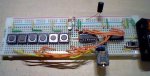
I used an AND gate to modulate the signal on to the carrier. Another way of doing this is to use additional transistors as shown in westaust55's IR tutorial. The output of the AND gate feeds into the base of an NPN transistor through a resistor and this transistor drives the LED.
This worked perfectly on a Freeview box and 2 TVs (all rebadged Vestels) and should work on most store brand (and Hitachi now?) TVs.
Cannot explain any more due to reaching the forum character limit.
Next thing to work on - modulating the signal onto the carrier inside the PICAXE rather than use external components.
RC-5 looks like an easy interface to bit bang. There are few bits and it uses manchester encoding rather than the popular alternative of varying pauses depending on whether the bit is a 1 or 0. That is important as it means that there is now only one time period value to guess rather than two values (you can't just use a pauseus command with the value pulled from the specification due to the overhead of the interpreter) plus the inverted part of the bit can be generated really easily.
I used a PICAXE-14M2 at 32MHz.
In this example code, signalpin is a pin variable (remember to set the pin as an output first!), bitperiod is a constant, flipbit/addressx/datax are bit variables. The flipbit bit variable should be toggled so that it indicates whether any interruption in the signal was because of something blocking the signal or because the button was released and pressed again.
The addressx bits control which device is to be controlled and the datax bits control what command is to be sent to the device.
Code:
send:
	signalpin = 1
	pauseus bitperiod
	signalpin = 0			'data6 + 1 for 7-bit commands
	pauseus bitperiod
	signalpin = 1			'data6 for 7-bit commands
	pauseus bitperiod
	signalpin = flipbit
	pauseus bitperiod
	signalpin = flipbit + 1
	pauseus bitperiod
	signalpin = address4 + 1
	pauseus bitperiod
	signalpin = address4
	pauseus bitperiod
	signalpin = address3 + 1
	pauseus bitperiod
	signalpin = address3
	pauseus bitperiod
	signalpin = address2 + 1
	pauseus bitperiod
	signalpin = address2
	pauseus bitperiod
	signalpin = address1 + 1
	pauseus bitperiod
	signalpin = address1
	pauseus bitperiod
	signalpin = address0 + 1
	pauseus bitperiod
	signalpin = address0
	pauseus bitperiod
	signalpin = data5 + 1
	pauseus bitperiod
	signalpin = data5
	pauseus bitperiod
	signalpin = data4 + 1
	pauseus bitperiod
	signalpin = data4
	pauseus bitperiod
	signalpin = data3 + 1
	pauseus bitperiod
	signalpin = data3
	pauseus bitperiod
	signalpin = data2 + 1
	pauseus bitperiod
	signalpin = data2
	pauseus bitperiod
	signalpin = data1 + 1
	pauseus bitperiod
	signalpin = data1
	pauseus bitperiod
	signalpin = data0 + 1
	pauseus bitperiod
	signalpin = data0
	pauseus bitperiod
	signalpin = 0
returnIf multiple devices need to be controlled then the addressx bits can be assigned to variables - if not then they can be constants. If 4 or less (2 or less if using data6) devices are to be controlled, the relevant addressx bits can use the remaining bit variables that are part of the same byte variable as the datax bits are part of allowing the device controlled and the command sent to both be set using a single let command. Any number of devices can be controlled this way if a word variable is used.
I will use the above technique in the example below that can control a TV and a set top box.
This example code can control six functions of the TV or STB using six buttons wired between the pins defined in the symbol definitions and 0V - the internal pullups are used. The datasent bit variable is used to determine whether to toggle the flipbit variable or not. The pause 800 added to the send sub is to create a delay between repeated executions of the send sub.
The pwmout command is used to generate a 36KHz carrier signal with ~30% duty cycle. The bitperiod constant sets the period of each half-bit and may or may not need tweaking to work with all devices for the reason described earlier.
The constants for the commands for the set top box are ORed with 128 to set the device bit when those constants are used eliminating the need for a second variable to set which device is used or to manually do this in code at runtime. Since they are constants, they are calculated by the compiler rather than processed by the PICAXE at runtime but doing it this way allows it to be easily seen what the command codes are for the different commands.
Code:
#picaxe 14m2
#no_data
#no_end
#terminal off

symbol pwmpin = B.2
symbol signal = B.0
symbol signalpin = pinB.0
symbol button1 = pinC.0
symbol button2 = pinC.1
symbol button3 = pinC.2
symbol button4 = pinC.3
symbol button5 = pinC.4
symbol button6 = pinB.5

symbol flipbit = bit0
symbol datasent = bit1

symbol command = b1
symbol data0 = bit8
symbol data1 = bit9
symbol data2 = bit10
symbol data3 = bit11
symbol data4 = bit12
symbol data5 = bit13
symbol device = bit15

symbol address0 = 0
symbol address1 = 0
symbol address2 = 0
symbol address4 = 0

symbol bitperiod = 570

symbol doubledigit	= 10
symbol standby		= 12
symbol mute			= 13
symbol PP			= 14
symbol volup		= 16
symbol voldown		= 17
symbol channellist	= 18
symbol down			= 19
symbol up			= 20
symbol left			= 21
symbol right		= 22
symbol PRup			= 32
symbol PRdown		= 33
symbol lastpr		= 34
symbol audiomode		= 35
symbol hold			= 41
symbol subcode		= 42
symbol size			= 43
symbol reveal		= 44
symbol update		= 45
symbol mix			= 46
symbol index		= 47
symbol menu			= 48
symbol yellow		= 50
symbol blue			= 52
symbol OK			= 53
symbol green		= 54
symbol red			= 55
symbol AVbutton		= 56
symbol text			= 60
symbol TVbutton		= 63

symbol STB_back		= 10 | 128
symbol STB_standby	= 12 | 128
symbol STB_mute		= 13 | 128
symbol STB_AV		= 14 | 128
symbol STB_volup		= 16 | 128
symbol STB_voldown	= 17 | 128
symbol STB_up		= 18 | 128
symbol STB_down		= 19 | 128
symbol STB_OK		= 20 | 128
symbol STB_left		= 21 | 128
symbol STB_right		= 22 | 128
symbol STB_wide		= 30 | 128
symbol STB_PRup		= 32 | 128
symbol STB_PRdown		= 33 | 128
symbol STB_EPG		= 34 | 128
symbol STB_subtitle	= 38 | 128
symbol STB_yellow		= 50 | 128
symbol STB_blue		= 52 | 128
symbol STB_menu		= 53 | 128
symbol STB_green		= 54 | 128
symbol STB_red		= 55 | 128
symbol STB_text		= 60 | 128
symbol STB_info		= 63 | 128

main:
	pullup %0001111100100000
	disconnect
	setfreq m32
	pwmout pwmpin,221,267
	do
		if button1 = 0 then
			[B]command = standby[/B]
			gosub send
			[B]command = PRup[/B]
			gosub send
			do : loop until button1 = 1
			pause 10
		elseif button2 = 0 then
			[B]command = AVbutton[/B]
			gosub send
		elseif button3 = 0 then
			[B]command = STB_PRdown[/B]
			gosub send
		elseif button4 = 0 then
			[B]command = STB_PRup[/B]
			gosub send
		elseif button5 = 0 then
			[B]command = voldown[/B]
			gosub send
		elseif button6 = 0 then
			[B]command = volup[/B]
			gosub send
		elseif datasent = 1 then
			flipbit = flipbit + 1
			datasent = 0
		end if
	loop

send:
	signalpin = 1
	pauseus bitperiod
	signalpin = 0
	pauseus bitperiod
	signalpin = 1
	pauseus bitperiod
	signalpin = flipbit
	pauseus bitperiod
	signalpin = flipbit + 1
	pauseus bitperiod
	signalpin = address4 + 1
	pauseus bitperiod
	signalpin = address4
	pauseus bitperiod
	signalpin = device + 1
	pauseus bitperiod
	signalpin = device
	pauseus bitperiod
	signalpin = address2 + 1
	pauseus bitperiod
	signalpin = address2
	pauseus bitperiod
	signalpin = address1 + 1
	pauseus bitperiod
	signalpin = address1
	pauseus bitperiod
	signalpin = address0 + 1
	pauseus bitperiod
	signalpin = address0
	pauseus bitperiod
	signalpin = data5 + 1
	pauseus bitperiod
	signalpin = data5
	pauseus bitperiod
	signalpin = data4 + 1
	pauseus bitperiod
	signalpin = data4
	pauseus bitperiod
	signalpin = data3 + 1
	pauseus bitperiod
	signalpin = data3
	pauseus bitperiod
	signalpin = data2 + 1
	pauseus bitperiod
	signalpin = data2
	pauseus bitperiod
	signalpin = data1 + 1
	pauseus bitperiod
	signalpin = data1
	pauseus bitperiod
	signalpin = data0 + 1
	pauseus bitperiod
	signalpin = data0
	pauseus bitperiod
	signalpin = 0
	pause 800
	datasent = 1
return- Standby (TV) - this button is done differently to the others because the TV will only come out of standby if PRup, PRdown or a channel number is used and not when the standby button is pressed again so sending both the standby and PRup commands in quick succession and not repeating this signal when the button is held down causes it to go into standby if it on and turn on if it is in standby.
- AV (TV) - cycles between the AV inputs and analogue TV mode
- STB_PRdown (STB) - P- on set top box
- STB_PRup (STB) - P+ on set top box
- voldown (TV) - decreases the volume on the TV
- volup (TV) - increases the volume on the TV
I used an AND gate to modulate the signal on to the carrier. Another way of doing this is to use additional transistors as shown in westaust55's IR tutorial. The output of the AND gate feeds into the base of an NPN transistor through a resistor and this transistor drives the LED.
This worked perfectly on a Freeview box and 2 TVs (all rebadged Vestels) and should work on most store brand (and Hitachi now?) TVs.
Cannot explain any more due to reaching the forum character limit.
Next thing to work on - modulating the signal onto the carrier inside the PICAXE rather than use external components.