I would like some feedback on this method of using C.0 (serial out) as an input . It works by connecting the DAC to the output pin, but not enabling the DAC . The pin is connected to VSOURCE+ through all the resistors in the resistor ladder by setting DACLPS = 1 and DACLEVEL to 0 . The bottom of the ladder is not connected to VSOURCE- . This is the low power setting so the ladder doesn't draw as much current . To use it as an input connect the pin to ground through a switch and 10K resistor . Use the READDAC command to determine if the switch is closed . The following test program returned readings of 250-255 with the switch open and 19-22 with it closed .
The voltage measured across the 9.8K resistor with the switch closed was .25 volts with a supply voltage of 4.3 volts . This comes out to .025 mA, so I don't think the pin is being loaded excessively . The datasheet shows 32 resistors of 5K each in the ladder . Using Ohms law, (4.3Volts - .25Volts) / .000025Amps = 162KOhms between the pin and VSOURCE+ . This is inline with the datasheet . I know this is not the intended use for the DAC, so I'd like other opinions .
Pertinent parts of PIC12lf1840 datasheet:
Section 17 for DAC
FIGURE 17-3 OUTPUT VOLTAGE CLAMPING EXAMPLES
REGISTER 17-1: DACCON0: VOLTAGE REFERENCE CONTROL REGISTER 0
Table 30-11 DAC electrical specs
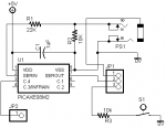
I have included my test program and schematic .
The voltage measured across the 9.8K resistor with the switch closed was .25 volts with a supply voltage of 4.3 volts . This comes out to .025 mA, so I don't think the pin is being loaded excessively . The datasheet shows 32 resistors of 5K each in the ladder . Using Ohms law, (4.3Volts - .25Volts) / .000025Amps = 162KOhms between the pin and VSOURCE+ . This is inline with the datasheet . I know this is not the intended use for the DAC, so I'd like other opinions .
Pertinent parts of PIC12lf1840 datasheet:
Section 17 for DAC
FIGURE 17-3 OUTPUT VOLTAGE CLAMPING EXAMPLES
REGISTER 17-1: DACCON0: VOLTAGE REFERENCE CONTROL REGISTER 0
Table 30-11 DAC electrical specs
I have included my test program and schematic .
Code:
'test using serout pin C.0 as an input by using dac
'
'connects C.0 pin to positive rail through all dac voltage divider resistors
'bottom of voltage divider is disconnected by setting DACEN = 0 , DACLPS = 1
'picaxe commands are
' daclevel 0
' dacsetup  %01100000

'use readdac to get voltage on pin
'if switch is open reading will be near max (255)
'if switch is closed it will be near 0 (I got 20)

'refer to section 17.4 of pic12lf1840 data sheet for details

'built on AXE021 PICAXE-08 PROTO BOARD
'after programming set jumper to route C.0 to 10K resistor and switch
'jumper C.4 back to serout of programming socket for serial output


#picaxe 08m2

setfreq m4


'prepare c.4 for serout (idle low)
low c.4
pause 1000


serout c.4,n2400_4,("Start",13,10)


daclevel 0
dacsetup %01100000	'connect pin to positive rail through all resistors in ladder

here2:
readdac b0
	serout c.4,n2400_4,(#b0,13,10)
	if bit7 = 0 then			'if less than 128 then switch must be closed
		serout c.4,n2400_4,("closed",13,10)
	else
		serout c.4,n2400_4,("open",13,10)
	endif
	pause 500

goto here2")