Hello
I have been trying to interface this ultrasonic distance finder module with a PICAXE 18x
I found two helpful code examples, and they both seem to do the actual sensing the same way. My code is
symbol trigger = 3
symbol echo = 6
symbol range = w1
main:
pulsout trigger, 2
pulsin echo, 1, range
pause 10
range = range * 10 / 58 ‘ multiply by 10 then divide by 58
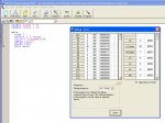
debug range
pause 500
goto main
My problem is that, although I am getting values in w1, they don't make sense. Eg... pointing at the celing the value is 7, when i place my hand over the sensor the value is 5, pointing it into the distance the value is 8, and all sorts of other obviously incorrect readings.
Unfortunately, there is not much on Google about interfacing this with the picaxe, and the datasheet isn't that helpful to someone who is a bit of a newbie like me.
Has anyone had any success with this module and a picaxe? If so, is my code wrong, is my module faulty, or is it something else?
Many thanks
I have been trying to interface this ultrasonic distance finder module with a PICAXE 18x
I found two helpful code examples, and they both seem to do the actual sensing the same way. My code is
symbol trigger = 3
symbol echo = 6
symbol range = w1
main:
pulsout trigger, 2
pulsin echo, 1, range
pause 10
range = range * 10 / 58 ‘ multiply by 10 then divide by 58
debug range
pause 500
goto main
My problem is that, although I am getting values in w1, they don't make sense. Eg... pointing at the celing the value is 7, when i place my hand over the sensor the value is 5, pointing it into the distance the value is 8, and all sorts of other obviously incorrect readings.
Unfortunately, there is not much on Google about interfacing this with the picaxe, and the datasheet isn't that helpful to someone who is a bit of a newbie like me.
Has anyone had any success with this module and a picaxe? If so, is my code wrong, is my module faulty, or is it something else?
Many thanks
")