PS2 optical mouse sensor availability

alband

Senior Member
Hi,

I'm planning to use an Avago optical mouse sensor for something (think it might actually be valuable to keep this secret for once!). Problem is, it is IMPOSSIBLE to get hold of Avago mouse sensors in the UK. A few sites sell avago stuff, but all "non stock". By far the easiest way is to buy a mouse just for it's sensor. However, I need to know what the sensor in the mouse is like before I buy it and most dealers aren't happy for you to disassemble their stock before you buy, no matter how much you tell them "Trust me, it'll be just fine".

So... I was shamefully hoping that some of you nice folk could have a peek around inside any of your mice? :confused: :p
Also, perhaps if someone had a spare mouse, or a broken mouse (though with a working sensor), it would be great to buy for someone on the forum, rather than an eBay seller (for once).

I'm wanting to interface it with a PICAXE so most USB mice wont work, and although most PS2 mice use Avago sensors, I'm looking for one with a small 8-pin type sensor, and if possible with a small lens-system too.

Is there anyone out there who would be willing? Huge thanks in advance for any help on this.

Cheers,
David.
 

SAborn

Senior Member
So... I was shamefully hoping that some of you nice folk could have a peek around inside any of your mice?
Also, perhaps if someone had a spare mouse, or a broken mouse
Humm, Blood and guts in the mice i checked, getting the covering of is messy too.

Spare mouse.....?? cat tucker

Broken mouse..... ?? we call them dead here, or again cat tucker.

it is IMPOSSIBLE to get hold of Avago mouse sensors in the UK
Try buying a mouse trap they are auto sensing, result = 1 mouse with flat sensors.

and if possible with a small lens-system too.
What now you want a mouse with contact lenses too, didnt know they made contacts for mice.
 

Captain Haddock

Senior Member
I just had a look in mine, unfortunately it's a trust wireless one with loads of crap (another circuit board) covering the sensor thats soldered on, I don't fancy going that far.
However thanks for inspiring me to dislodge the big furball thats been wedged in there for ages, works much better now.
 

alband

Senior Member
Very good SAborn:rolleyes: Sorry to confuse but I was actually referring to computer mice.

I can give you some part numbers Goeytex but I'm not sure they'd help. My only requirements are really that it's as small as possible, and obviously, the higher the spec the better. However, from what I've learned the part numbers aren't marked on the devices (pain!), only the Avago symbol. The sensors come in laser or LED types. Any of the laser ones would be great but more likely to be in a gaming mouse so unlikely to be in something one would be willing to take apart. The smallest size the LED based ones come in is 8pin DIP packages and they're are what I'm really looking for. There's two of this type currently made by Avago and their part numbers are at the bottom, but there are several that are no longer in production so I can't get part numbers for but which will do just fine. So basically anything from Avago that is 8 pin is great.

These are the current LED ones:
ADNS-5020-EN
ADNS-5050

And the laser ones are:
ADNS-7530
ADNS-7550
ADNS-9500
ADNS-9800


Thanks,
David
 

alband

Senior Member
I just had a look in mine, unfortunately it's a trust wireless one with loads of crap (another circuit board) covering the sensor thats soldered on, I don't fancy going that far.
However thanks for inspiring me to dislodge the big furball thats been wedged in there for ages, works much better now.
Sorry, missed your reply. Thanks for trying and no problem, glad you got something out of it!
 

alband

Senior Member
No, not really. I checked Avago's site for something like "who uses us" but couldn't find anything. All I've gathered is that most standard mice use them, though there's also quite a few with Cypress ones.

I've tested a sensor from Avago from a Dell mouse and it worked well (hence wanting to use them) but it was too big to use and was USB-type, so couldn't be interface with a PICAXE. I wouldn't be confident that ALL Dell mice use them though just from that one, plus they could use one of the larger Avago sensors.

Cheers
 

alband

Senior Member
Intestines? :confused:

I've never ordered from alibaba, I thought it was for companies wanting suppliers. Does it work small scale too? I'm dubious about whether that's the right part. The part no. is fine, but the picture(s) aren't right at all and the manufacturer is "AD, Analogue Devices presumably. $2 isn't a bad price though if it does work. However I would also need the correct lens and LED clip for that sensor, which don't appear to be anywhere. I think it would be easier to get hold of a mouse somehow, just need to find the mouse.
Sorry SAborn, but thanks for trying :)
 

alband

Senior Member
It's quite easy if you know how ;)
The ones I'm looking for (avago, non-USB) interface to their host controller by SPI. Presume you know more about that than me! I hope I'm not missing something.

The frustrating thin is I've got a sensor working here but it's got USB built in and no other interface. It'll do fancy things like check for buttons to be pressed and flash lights but I can't interface with it.

Since there seems to be somewhat of a lack of "willing volunteers" (unsurprising I suppose) has anyone got any other ideas about how to find out what sensor a particular mouse might have. Non of the specs for mice that I can find are detailed enough to say what sensor they use and searching for "PS/2 mouse avago" either brings up lots of avago data sheets and pages or one single mouse that mentions the word avago in the description but doesn't say which part no.

Any ideas?

Cheers.
 

Haku

Senior Member
This is in my Labtec 800 optical mouse, the 8 pin sensor connects to another IC on the other side of the board which appears to handle the USB side of things (and PS/2 as it came with an adaptor).


Buzby

Senior Member
.... connects to another IC on the other side of the board which appears to handle the USB side of things (and PS/2 as it came with an adaptor).
IIRC, that other chip magically PS/2 serial or USB, depending on the state of some pin at startup.

Then you've got a slightly less difficult challenge, PS/2 on PICAXE, instead of USB !
 

alband

Senior Member
Thanks Haku. Good to know the guts of at least one mouse. Trouble is, I can't find what chip that is from the markings. It doesn't have the Avago symbol so I don't think it's from them. Given it appears to be interfacing with a controller though, one would guess it uses something like I2C or SPI, which is easily PICAXEable. I would want to comunicate directly swith the sensor as space is tight, so what protocol is used with a the computer doesn't actually matter. However, all the Avago USB sensors have USB on-chip, so PS/2 mice are more likely to be interfaceable.

I'm hoping to see a friend on Monday who apparently has a whole hoast of old PS/2 mice and is willing to let me disect them, given that 1) he knows me and knows I can do this stuff and 2) I said I'll buy any I break (mostly latter?). If I find no luck with those then that Labtec of your's Haku looks like a viable option. The lens assembly looks pretty small from what I can see and it seems pretty inexpensive if I've got the right one?
Great macro shot btw.

Thanks,
David.
 

Haku

Senior Member
@alband, yes that's the one, it's my current favourite brand/model of mouse, a while back I managed to get some from a 99p store, I have a spare parts one which got some crush damage and doesn't show up on the PC but the sensor still appears to work as the red LED goes brighter when it senses movement which you're welcome to, and if you get it working then post the wiring diagram and example code for us to use :)
 

alband

Senior Member
@ Buzby: That lego thing got me excited at first, but the guy didn't mention WHICH mouse he used (either of them!). The second one he tried which was interfaceable would have been great, but he didn't say which mouse it was, so doesn't really help my problem. Interesting read though and it adds another part number to the working list that are no longer in production: ADNS‐2083

@ Haku: I might take you up on that spare one, but I'll wait to see if any of the ones my friend has are recognisably Avago-branded. I'd rather use one I know works and can find a datasheet for than try to work out everything from scratch. Either way, I can post the code for it, but I doubt it'll be too difficult. Hopefully should just be one of those cases of read the datasheet x10 try it x100 and you're there.

@ boriz: You know how much I love eBay huh? Things is about something like that, is that it's greatest strength (the low price) is also it's weekness. At that price, it's more likely to be a one-chip solution (I think?). Ergo, it'll only be USB controllable. If all doesn't go well, I am going to have to start buying and trying, but I think I'd start with a PS/2 type mouse, and pay a bit more, since I'll be sure there's no USB in sight to contend with.

Just as a matter of interest. When I was doing some research into this stuff at first, I read a comment on a post of a hack that read something like "You could use one of these sensors along with a cheap inferometer to create a very accurate CNC rig". Sounded very interesting. I believe an inferometer uses the finge patterns of light to take mesurements, thus allowing easy observation of distances that are comprable to the wavelength of the light used. So you'd have your inferometer set up to measure the distance between a fixed point on the rig and your moving drill bit thing. Project the fringes of the inferometer onto the mouse sensor. The fringes would change very rapidly but the mouse sensors can keep up with that. If I understood that correctly, that could make for a VERY accurate CNC rig? Not sure where you'd go about getting a "cheap" inferometer of that kind from, or how you'd managed to keep the accuracy of the rest of the rig up to that standard, but interesting non-the-less.
 

Svejk

Senior Member
A PS2 optical mouse from flea market will do the trick. Comms from Avago IC's are SPI (at least the ones that I have) and some have quadrature output for x and y. Parallax sells a kit for about $20, do a search. Interfacing is easily picaxable.
 

alband

Senior Member
Well bugger. Friend's mouse was a ball mouse, not optical D: It's annoying when you have twon projects going and both hit a dead wall! Right, back on the horse.

Done some more googling for those part numbers on top of your chip Haku. Still can't find it, but found this: http://blog.jgc.org/2012/09/conversion-of-cheap-optical-mouse-to.html

At a guess, I'd say that's the same brand of mouse as your's, not the exact same one, but it's using the very same sensor. Although there don't appear to be any datasheets or anything for that sensor (MCS-12085) it's older brother does seem to exist on the web (MCS-12086). The author of that page thinks the only difference between them is that the 12086 doesn't need an external resonator. I do hope that's the case, as the specs for the 12086 look to be just what I need, especailly the 8g acceleration rating. The 12086 is also, coincidently, the same chip used on that Parallax board you referred to Svejk. I only managed to find that board for about £30, so off budget. I also found a breakout from Sparkfun for an Avago sensor but it's no longer stocked anywhere.

So Haku, could I take you up on your offer of your crushed on please! :) how crushed is it though? Are the lens and LED ok, I could probably find another LED somewhere, but the lens would be hard to replace.

Here are the datasheets for the 12086 I'll be using; http://forums.parallax.com/attachment.php?attachmentid=67975&d=1266753768 http://www.parallax.com/Portals/0/Downloads/docs/prod/hardware/28560-MouseSensorKit-v1.0.pdf

I'm sure working code shouldn't be to difficult to get give the author of that page has already managed with with "Ar-duino".

Thanks everyone, would be lost without this place!
David
 

Haku

Senior Member
@alband, scrollwheel snapped off, middle button broken & circuitboard cracked a little right next to there which I think is preventing it from showing up & working on a PC, but the sensor appears to work fine as when it's plugged in the LED goes from dim to bright when it senses movement. It's just what you see with the attached USB cable, lens is there, no top half. Message me your address and I'll post it.


boriz

Senior Member
Good link Larry. Also found this: http://www.electronics-base.com/index.php/general-description/communication/111-the-ps2-protocol-used-by-mousekeyboard

"The clock frequency must be in the range 10 - 16.7 kHz. This means clock must be high for 30 - 50 microseconds and low for 30 - 50 microseconds.. If you're designing a keyboard, mouse, or host emulator, you should modify/sample the Data line in the middle of each cell. I.e. 15 - 25 microseconds after the appropriate clock transition."

Looks too fast for Picaxe BASIC. Maybe the mouse clock could be hacked? Replace xtal? Divider? Maybe it could be provided externally, like from a 555 or Picaxe?

Seems the keyboard protocol is very similar. Maybe the Picaxe firmware could include mouse reading alongside keyboard reading?
 

alband

Senior Member
See if you can guess if this message is about it working or not working... I am at my wit's end!

@boriz & Larry: I'm interfacing directly with the chip so I don't need the PS/2 info, although I appreciate the thought and am sure others will find it useful.

And boriz, I'll let you know when I'm rich and have firm patent down!

Haku, you're awesome! It arrived this morning and I've been working on it all this afternoon. However, you guessed it, no luck as yet. So here's the low down...

These are the various datasheets and sources I'm using:

Arduino program for this exact chip that works. This is useful for seeing the timing of the serial protocol, as it has been bit-banged: https://github.com/jgrahamc/mcs12085/blob/master/mcs-12085.cpp
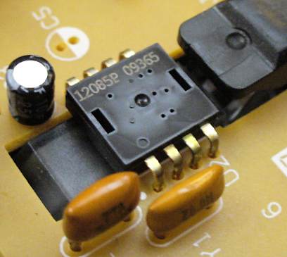
This is for a slightly different chip. The only difference seems to be that my chip needs and has an external resonator. Page 4 gives a circuit diagram which is compatible with my chip: http://forums.parallax.com/attachment.php?attachmentid=67975&d=1266753768
Datasheet for the previously mentioned Parallax kit with the previously mentioned slightly different sensor. Pages 10 and 11 are also useful for serial timings and register addresses: http://www.parallax.com/Portals/0/Downloads/docs/prod/hardware/28560-MouseSensorKit-v1.0.pdf

What I know about the sensor's serial protocol...
  • The max clock frequency is probably 2Mhz so all hspi speeds should work. (1st link "cycle time" and 2nd link p6)
  • Clock idles high. (3rd link page 11 and 1st link code)
  • MSB first.
  • Standard operating program would be:
    1. Power on and wait 100ms
    2. Set resolution (optional)
    3. Check "status" register
    4. If "status" indicates movement, check "dx" and "dy" registers
    5. Back to 3
  • To read "Status" register, you clock out "register address as eight bits, most significant bit first, with bit 7 cleared to zero." So in this case you would use
    Code:
    hspiout (%00010110)
    then you clock in the next 8 bits.

Things I'm not sure about:
  • When bits are sampled by the sensor relative to the clock. 3rd link p10 would indicated that data is sampled on the rising clock edge however I don't know that and can't test it - hspisetup has no way of changing when the data is sent relative to the clock pulses, and when I try to bit bang, I just get random results [more later].
  • When bits are sent by the sensor relative to the clock. Again 3rd link p10 would indicated it's on a rising clock edge, but I haven't successfully read any data form it so don't know.

Given the above, I think this should work as a setup and don't know why it doesn't:

Code:
SYMBOL rw = bit0
SYMBOL dx = b1
SYMBOL dy = b2
SYMBOL quality = b3
SYMBOL status = b4
SYMBOL config = b5
SYMBOL operation = b6


startup: hspisetup spimode10e, spislow

sertxd ("start",cr,lf)
pause 500

main:
gosub mousestatus
sertxd (#status,cr,lf)
goto main

mousestatus:
hspiout (%00010110)
hspiin (status)
return
However, all I get from the terminal is "Start 0 0 0 0 0 0 0 0..."
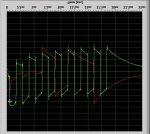
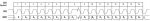
One thing of note though is that I was able to take my soundcard scope to this a very low speeds and if the sensor does indeed read on the rising edge of the clock, it will have trouble as the data line switches on the rising edge. No way of changing this that I can find. I've attached the scope screenshot. I've filpped the image because for some reason the soundcard reads everything inverted (tested 100% certain). The red is data, green is the clock and the first 3 bits of data are 0's decaying across the three bits.

I've tried all the different hspimodes though I'm pretty certain it should be "10e" and i've tried slowing the speeds right down using all three spispeeds (and "255") and using setfreq as low as "k31".

I have also tried completely bit banging everything with high's and lows (second attached code). However, all I just get seemingly random numbers from the terminal window on reading, I don't know why. I've also tried using the spiin and spiout bit bang commands but the spiin command doesn't work with a clock that idles high, on the firmware I'm using (sod's law). So I can't test if that's working either.

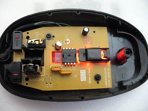
I'm using a 40X1 with apparently quite old firmware. I'm sure of the circuitry. The sensor is still in the mouse with all of that circuitry except, I've cut through the two communication lines (clock and bi-data) and have soldered long wires to those two legs which are breadboarded to the PICAXE. I've with and without pullup/down resistors (1kohm). The USB cable of the mouse is connected to the breadboard securely by it's ground and VDD, on the same supply as the breadboard. Power supplys are steady and well used and tested.

Any ideas because i'm completely stuck and shattard from trying.

Huge thanks in advance, I could really use some help on this as I don't fell I have any leads or ideas at all.

David
 

Attachments

alband

Senior Member
Man Haku, you just keep giving! That would be excellent. I've done some more work on the other one, but I still just can't get anything from it. I had a look through the ADNS-2610 datasheet as they're meant to be equivalent parts. The only thing it said that I wasn't doing was to have a sizeable gab between each read or write, but adding that gap has made no difference.

I've tried to replicate the program from here as best as possible because I KNOW that works with that exact chip, but I still get nothing. I've attached that program if anyone wants a look.

Thanks again Haku,

David.
 

alband

Senior Member
Morning all,

I've had a while off this project as I've been busy. I've tested the three modules Haku sent me (thank you Haku) but I haven't had any success. I can only get one of the modules to give any indication of working, in that the LED comes on and goes off with movement the way you'd expect. I haven't had time yet to check the LED pin on the other two, but from examining the traces and doing bits of fault finding, I suspect the chips are dead - could be wrong.
Either way, I can't get any of them to respond to the PICAXE. Currently I working on the most basic program I can which is just a bit bangged routine, pretty much strait from the datasheet. I think it's sound but I'd appreciate it if anyone could have a scan over it for any glaring mistakes.
I'm sure of my connections to the chips and the circuitry in general. I'm using the boards the chips came in, resonator, caps etc. and then wiring the SDIO and SCK pins directly to the PICAXE's - checked with multimeter. Only things I'm not sure of are whether to use any pull-up/downs (not using any atm) and whether to have the SDI and SDO buffered together with resistors or just connect them all together, I've tried both though.
I'm using a brand new 28X2 at setfreq 16m for a bit more accuracy, though I might get rid of that as I don't think it's doing much.

Thanks in advance. Determined to see this through as I know it could be useful to others.

David.

http://www.avagotech.com/docs/AV02-1184EN

Code:
setfreq m16

SYMBOL SDO = C.5
SYMBOL SDI = C.4
SYMBOL SCk = C.3
Symbol tick = b2
Symbol D7 = bit0
Symbol D6 = bit1
Symbol D5 = bit2
Symbol D4 = bit3
Symbol D3 = bit4
Symbol D2 = bit5
Symbol D1 = bit6
Symbol D0 = bit7


tick = 6

main:

High SCK
High SDO

pause 200 'tSPTT

Low SDO
pause 1
Low SCK
pauseus tick
High SCK
pauseus tick
Low SCK
pauseus tick
High SCK
pauseus tick
Low SCK
pauseus tick
High SCK
pauseus tick
Low SCK
pauseus tick
High SCK
pauseus tick
Low SCK
pauseus tick
High SCK
pauseus tick
Low SCK
pauseus tick
High SCK
pauseus tick
Low SCK
pauseus tick
High SCK
pauseus tick

High SDO

Low SCK
pauseus tick
High SCK
pauseus tick

pauseus 6

input SDO
input SDI

pauseus 300  ' tHOLD

Low SCK
pauseus tick
High SCK
let D7 = SDI
pauseus tick
Low SCK
pauseus tick
High SCK
let D6 = SDI
pauseus tick
Low SCK
pauseus tick
High SCK
let D5 = SDI
pauseus tick
Low SCK
pauseus tick
High SCK
let D4 = SDI
pauseus tick
Low SCK
pauseus tick
High SCK
let D3 = SDI
pauseus tick
Low SCK
pauseus tick
High SCK
let D2 = SDI
pauseus tick
Low SCK
pauseus tick
High SCK
let D1 = SDI
pauseus tick
Low SCK
pauseus tick
High SCK
let D0 = SDI
pauseus tick

sertxd ("%",#D7,#D6,#D5,#D4,#D3,#D2,#D1,#D0,cr,lf)

Goto main
 

SAborn

Senior Member
Is there a reason why you use
"Low SCK
pauseus tick
High SCK
pauseus tick"

And not "pulsout"

Is the SDO not an input pin. if so why send it high/low as that would set it as an output pin.
Then this thread is getting old now and i forget what was discussed prior.
 

hippy

Technical Support
Staff member
I'm not familiar with these sensors nor their protocol, but it seems you would benefit from having a single SDIO pin for your PICAXE, along with routines which write and read data.

Figure 13 for example can then be coded as follows which is much easier than trying to work through a long list of explicit commands and whether you have the right data in those ...

data = %10000000 : Gosub WiteData
data = %01000000 : Gosub WiteData

In your code it would be helpful to state what you are writing and why, what in the datasheet relates to that and justifies it. The code you have I guess is effectively ...

data = %00000000 : Gosub WiteData
Gosub ReadData : b0 = data

In your current read code your "let D7 = SDI" etc won't work because SDI is a numeric pin number value, not the pin level. You also seem to be reading in lsb first order (D7/bit0 .. D0/bit7) when the data seems to be msb first. Though the SERTXD prints it in msb on the left format 'b0' value will be msb on the right; very confusing.

I would also suggest it's hard to develop code for sensor chips which may be faulty; far better to start with known working chips. At least that way you can go back to checking it still works as it's meant to be used and can look at what is sent on a working system compared to how you are doing things.
 

Goeytex

Senior Member
This sensor uses the same pin for SDO and SDI (SDIO). So the Picaxe needs to switch the data pin to an input after sending its 8 byte command to to the sensor and then use that same Pin to receive the data in to the Picaxe. I am wondering why two pins are used on the Picaxe for SDO and SDI.

I suppose that two pins Picaxe pins could be used, but SDI would need to be floating (High Z) when SDO is an output and SDO would need to be floating (High Z) when SDI is receiving data. This assumes that SDO and SDI are tied together.

It might be helpful to know how the sensor is connected to the Picaxe.
 

alband

Senior Member
Go it working. The thing wrong with the previous code was that
"let D7 = SDI" etc won't work because SDI is a numeric pin number value, not the pin level
Thanks Hippy. Changed that and it worked.

The sensor uses a normal SPI interface, so I planned to use hspi commands so I was using the two seperate pins that hspi uses for data in/out.

Didn't think to use pulsout, I just wrote it really simply to avoid doing anything clever that I could fowl up - haven't done any BASIC for a while.

As I say the above code wasn't something I'd use, I'm aware it's ineligant and clunky, I was just trying to get the thing working. Now that I have got it working though, I've written read/write routines and a more useable program with pleasing results. Call it a proof of concept. I now need to work on the maths and I want to get some kind of interface to the computer to visually demonstrate it's accuracy and speed etc. I'd like to have something like a dot moving around in a square on scree, just to deamonstrate movement. Also I'd like to make a live graph like a siezmometer that shows the "Q" level. This represents how well the sensor can see the surface it's on. And the thrid thing is to get a complete readout of what the sensor sees (camera style).

I'm sure I can work something up myself with VB. When I just joined this forum as an ignorant sprat I did a project with a PICAXE moving the mouse around using VB so I can use that. It was really clunky though so if anyone knows of a good way to do the kind of thing I'm thinking of I'd love to here it.

Mean-time, I'll get to work and here's the code. Thanks agian and Enjoy :)

Code:
setfreq m8

SYMBOL SDO = C.5
SYMBOL SDI = C.4
SYMBOL SCk = C.3
Symbol D7 = bit0
Symbol D6 = bit1
Symbol D5 = bit2
Symbol D4 = bit3
Symbol D3 = bit4
Symbol D2 = bit5
Symbol D1 = bit6
Symbol D0 = bit7
Symbol datain = b0
Symbol dataout = b1
Symbol dy = b2
Symbol dx = b3


startup: hspisetup spimode11, spifast

High SCK
High SDO
High SDI

pause 100 'tSPTT

main:
dataout = %00000001
Gosub MouseRead

If datain != %00000000 Then
	dataout = %00000010	'Set Address for dy
	Gosub MouseRead
	dy = datain			'Save dy value
	dataout = %00000011	'Set Address for dx
	Gosub MouseRead
	dx = datain			'Save dx value
	sertxd ("dy=",#dy," dx=",#dx,cr,lf)
Else
sertxd ("%",#D0,#D1,#D2,#D3,#D4,#D5,#D6,#D7,cr,lf)
Endif
Goto main

MouseRead:
hspiout (dataout)
pauseus 3
input SDO	'Set High Impendance
input SDI
pauseus 300  ' tHOLD
hspiin (datain)
High SDO	'Return Bus from HighZ to High State
High SDI
pauseus 100	'Between consecutive R/W
Return

MouseWrite:
hspiout (dataout)
pauseus 3
pauseus 300  ' tHOLD
hspiout (dataout)
High SDO
High SDI
pauseus 100
Return
N.B the write routine is untested
 

Goeytex

Senior Member
Alband,

I looked at the Avago datasheet and it says regarding SPI ...

"The microcontroller changes SDIO on falling edges of SCK. The ADNS-2610 reads SDIO on rising edges of SCK".​

If I am not mistaken, that correlates to spimode00 instead of spimode11
 

alband

Senior Member
Using post 16 in this (which I KEEP referring to) and the manul's section on hspisetup, I came to the conclusiong of mode11. I changed my mind 3 times over the course of this though.

My reasoning is:

The clock idles high, so that's the 2nd and 4th traces from the top on Hippy's image. Hence CKP=1.
The two traces in the middle show when a PIC sends data relative to the above clocks.
From the datasheet: "SDIO is changed on falling edges of SCK and read on every rising edge of SCK", so the sensor want to read data when the clock rises and expects data to be read when the clock rises.
Again looking at the two traces in Hippy's image, looking at the latter one, when the clock rises, the SDOx line is just about to change so not a great time for it to be read. Therefore using the 2nd out of those four traces would be best. Hence CKE=0.
Then the two traces at the bottom show when the PIC would sample data relative to those clock traces at the top. The sensor said it wants it to be read on rising edges and the only one that samples on rising edges of our chosen clock trace is the 1st of the two, corresponding to SPM=0.
So from the PICAXE manual:
spimode11 (CKP=1, CKE=0, SMP=0)
which fits.

Also for reference (nice to have all relavent info in one post). This is a "read" operation from the datasheet:
Capture.JPG


I've managed to get a VB program working when moving the mouse moves a small dot around in a box. It's a tad slow, I'd say about 10fps or so - bit slower than how fast my cursor updates anyway. If I make circles with my cursor, I see about 12 cursors in the loop; with my dot I only see about 7. Can't work out a way to speed it up, but it's pleasingly precise.
I'm working on a sQUAL readout now. Unless anyone is desperate to have a go, I'll finish that and the camera readout before I post code.

Cheers,
David.
 

hippy

Technical Support
Staff member
The sensor uses a normal SPI interface, so I planned to use hspi commands so I was using the two seperate pins that hspi uses for data in/out.
That makes sense. Use the same I/O pins as used for HSPI and if it works when software bit-banged it should work with HSPI as well.

In this case it most likely won't, because you explicitly make SDO an input when reading SDI ( or SDO as an output will short with the sensor as an output too ) and HSPI won't do that.

You can keep SDO as an output and use a diode and pull-up to make it open-collector or open-emitter ( so it floats and behaves like an input ) but I'm not sure you can achieve that in all circumstances for HSPI. It likely depends on the mode, what commands are sent and what level SDO is left at. You could achieve it with extra hardware.

PICmicro hardware ( and therefore PICAXE ) is designed for traditional SPI which always clocks data in while clocking data out, and isn't designed for the variant which uses a single pin and only allows comms in one direction at a time.
 

alband

Senior Member
Ummmm, I got it working though.

I've finished messing with VB for the time being. Managed to achive two of my three goals. Got a nice little white dot moving around in a square, just like the cursor, albeit a bit slow. And I've added a little bar graph thing (like audio level indicators) to show how good the sensor's quality. I worked on the camera thing for a while, but I couldn't find a good way of doing it in VB. I'm prettyr sure I could read the data into a text file and convert it into a JPG, but there's no need for the time being.

I've attached the code I'm using for the PICAXE. I just wrote two programs for the PICAXE, one for reading the mouse, the other for reading the "sQUAL" thing. Could be bothered to get bi-directional coms from the PC to the PICAXE when it was just for development and wouldn't ultimately be needed. Not sure how to attatch a VB program. I've attached what it calls a "Project Template". I believe if you unzip it somewhere and click on the ".vbproj" file, it'll open up ready to be built. You'll have to change the COM port to match you own.

That's it for now. I've got it up and running with the PICAXE so I can now move on to trying to incorporate it into that "valueable" idea I had in the first place. Thanks again Haku if you're still reading, and Hippy, even if you seem to have missed a couple of posts, couldn't have done it without either of you.

Cheers,
David.
 

Attachments

Top